
FSF-5050 Series · SAW Bandpass Filter
440, 441, 442 & 446 MHz SAW Bandpass Filters
FSF-5050-440M · FSF-5050-441M · FSF-5050-442M · FSF-5050-446M
Select the frequency, bandwidth definition and operating range for your RF receiver.
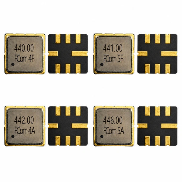
Model Selection
Four Frequencies, Distinct Selection Criteria
Bandwidths at different attenuation levels are not directly interchangeable. Select by the complete filter specification, including temperature and test conditions.
3 dB bandwidth
FSF-5050-440M
440 MHz
Specified center frequency
- 3 dB bandwidth (Min. / Typ.)
- 19 MHz / 23.3 MHz
- ILmin (Typ. / Max.)
- 1.4 dB / 2.8 dB
- Operating temperature
- −40 to +85 °C
2 dB bandwidth
FSF-5050-441M
441 MHz
Specified center frequency
- 2 dB bandwidth (Min. / Typ.)
- 19 MHz / 22.3 MHz
- ILmin (Typ. / Max.)
- 1.5 dB / 2.8 dB
- Operating temperature
- −40 to +85 °C
1 dB bandwidth
FSF-5050-442M
442 MHz
Specified center frequency
- 1 dB bandwidth (Min. / Typ.)
- 16 MHz / 20 MHz
- Insertion loss (Typ. / Max.)
- 1.5 dB / 3.0 dB
- Operating temperature
- −55 to +85 °C
Specified passband
FSF-5050-446M
446 MHz
Specified center frequency
- Specified passband
- 442–450 MHz (fC ±4 MHz)
- Insertion loss (Typ. / Max.)
- 2.3 dB / 4.5 dB
- Operating temperature
- −10 to +50 °C
Bandwidths at different attenuation levels are not directly interchangeable. Select by the complete filter specification, including temperature and test conditions.
Electrical Specifications
Six Key Parameters per Model
“—” means the source does not specify a value for that column; it does not mean zero. Typical values are design guidance. Final production specifications and tolerances are defined by the applicable official test limits and shipment CoC.
FSF-5050-440M
Scroll horizontally to view all columns.
| Parameter | Min. | Typ. | Max. | Unit | Definition / condition |
|---|---|---|---|---|---|
| Center frequency | 440 | MHz | Specified center frequency; no Min./Typ./Max. classification | ||
| Minimum insertion loss, ILmin | — | 1.4 | 2.8 | dB | ILmin; minimum passband loss |
| 3 dB bandwidth | 19 | 23.3 | — | MHz | Relative to ILmin |
| Amplitude ripple | — | — | — | dB | Not specified |
| Operating temperature | −40 | — | +85 | °C | Operating limits |
| Test source / load impedance | — | — | — | Ω | Each 50 Ω; test condition, not specified device impedance |
Electrical reference temperature: 25 °C. Insertion loss is ILmin, the minimum passband loss; the 3 dB bandwidth is measured relative to ILmin.
FSF-5050-441M
Scroll horizontally to view all columns.
| Parameter | Min. | Typ. | Max. | Unit | Definition / condition |
|---|---|---|---|---|---|
| Center frequency | 441 | MHz | Specified center frequency; no Min./Typ./Max. classification | ||
| Minimum insertion loss, ILmin | — | 1.5 | 2.8 | dB | ILmin; minimum passband loss |
| 2 dB bandwidth | 19 | 22.3 | — | MHz | Relative to ILmin |
| Amplitude ripple | — | — | — | dB | Not specified |
| Operating temperature | −40 | — | +85 | °C | Operating limits |
| Test source / load impedance | — | — | — | Ω | Each 50 Ω; test condition, not specified device impedance |
Electrical reference temperature: 25 °C. Insertion loss is ILmin, the minimum passband loss; the 2 dB bandwidth is measured relative to ILmin.
FSF-5050-442M
Scroll horizontally to view all columns.
| Parameter | Min. | Typ. | Max. | Unit | Definition / condition |
|---|---|---|---|---|---|
| Center frequency | 442 | MHz | Specified center frequency; no Min./Typ./Max. classification | ||
| Insertion loss | — | 1.5 | 3.0 | dB | IL; no additional passband interval stated |
| 1 dB bandwidth | 16 | 20 | — | MHz | As specified; reference level not explicitly stated |
| Amplitude ripple | — | — | — | dB | Not specified |
| Operating temperature | −55 | — | +85 | °C | Operating limits |
| Test source / load impedance | — | — | — | Ω | Each 50 Ω; test condition, not specified device impedance |
The FCom datasheet specifies 1 dB bandwidth but does not state a reference measurement temperature or explicitly define the bandwidth reference level. Do not substitute the 25 °C or ILmin notes from another model.
FSF-5050-446M
Scroll horizontally to view all columns.
| Parameter | Min. | Typ. | Max. | Unit | Definition / condition |
|---|---|---|---|---|---|
| Center frequency | 446 | MHz | Specified center frequency; no Min./Typ./Max. classification | ||
| Insertion loss | — | 2.3 | 4.5 | dB | fC ±4 MHz; 442–450 MHz |
| Specified passband | — | — | — | MHz | 442–450 MHz; not a specified 3 dB bandwidth |
| Amplitude ripple | — | 0.3 | 2.5 | dB | fC ±4 MHz; 442–450 MHz |
| Operating temperature | −10 | — | +50 | °C | Operating limits |
| Test source / load impedance | — | — | — | Ω | Each 50 Ω; test condition, not specified device impedance |
Insertion loss and amplitude ripple apply over fC ±4 MHz (442–450 MHz). A 3 dB bandwidth value and reference measurement temperature are not provided. Operating range is −10 to +50 °C; the separate storage range is −40 to +85 °C.
Device input and output impedances are not specified in the FCom datasheets. Refer to the four-page combined PDF for the source notes and package information; confirm any additional rejection or maximum-rating requirement against the applicable FCom production specification.
Typical Applications
Application Fit
Receiver front-end filtering
Select the wanted RF band before subsequent receiver stages. Check insertion loss and the required out-of-band rejection for the chosen model.
RF signal selection
Evaluate the 440, 441, 442 or 446 MHz option against the signal bandwidth and its allowable attenuation. Preserve the model-specific bandwidth definition.
Custom UHF designs
Use the relevant frequency option for band selection in a custom RF design. Include the operating temperature and actual source/load conditions in the selection review.
Integration Notes
Confirm the Interface Before PCB Release
Test terminations
All four FCom pages state 50 Ω test source and load conditions. Their intrinsic input and output impedances remain unspecified.
Matching conditions
The 440, 441 and 442 MHz measurement circuits use no external matching. The 446 MHz model explicitly requires no matching network for the specified 50 Ω operation.
Design limits
Check the selected model’s operating range, signal and DC limits, pin connections and layout against the applicable production specification. Keep storage limits separate from operating conditions.
Package & Pin Assignment
Mechanical Interface
The four FCom datasheets show a 5.0 × 5.0 mm, 8-pad leadless SMD package with a maximum height of 1.5 mm.
Refer to the applicable drawing in the combined PDF for dimensions. Confirm the mounting view before PCB release; the product photograph does not establish pin orientation.
Pins 2 and 6 are labeled Input/Output. Confirm signal direction and the complete ordering configuration. Contact FCom for other pin-configuration requirements.
| Pin(s) | FCom function |
|---|---|
| 2 | Input / Output |
| 6 | Input / Output |
| 1, 3 | Ground |
| 5, 7 | Ground |
| 4 | Case ground |
| 8 | Case ground |
Selection and Design-In Support
Discuss Your Signal Path with FCom
Share the model or center frequency, required passband or bandwidth with its attenuation level, source/load requirements and temperature range. Include input signal and DC conditions, sample quantity and estimated usage.
Confirm the applicable production specification, pin configuration and complete ordering code before design release.
Engineering Questions
Frequently Asked Questions
Can I compare the four bandwidth figures directly?
No. FSF-5050-440M uses a 3 dB bandwidth, FSF-5050-441M a 2 dB bandwidth, and FSF-5050-442M a 1 dB bandwidth. FSF-5050-446M specifies performance over 442–450 MHz without a 3 dB bandwidth value. Keep the attenuation level and reference definition with each value.
Are the input and output impedances specified as 50 Ω?
The FCom datasheets specify 50 Ω test source and load terminations. The device input and output impedance entries remain undefined. A 50 Ω test environment is not an independent intrinsic-device impedance specification.
Is external matching required?
The 440, 441 and 442 MHz FCom pages state that their measurement circuits use no external matching. The 446 MHz page explicitly states that no matching network is required for 50 Ω operation. Check the source/load conditions and PCB implementation for the selected model.
Do all four models operate from −40 to +85 °C?
No. FSF-5050-440M and FSF-5050-441M specify −40 to +85 °C, FSF-5050-442M specifies −55 to +85 °C, and FSF-5050-446M specifies −10 to +50 °C. The 446 MHz storage range of −40 to +85 °C is not its operating range.
Are all electrical values measured at 25 °C?
The 440 and 441 MHz datasheets explicitly state a 25 °C electrical reference temperature. No reference measurement temperature is stated for the 442 or 446 MHz pages. Typical values are design guidance; confirm the applicable production test limits and shipment CoC.
What information should I include in an inquiry?
Provide the selected model or center frequency, required passband or bandwidth with its attenuation level, source/load requirements, operating temperature, input signal and DC conditions, sample quantity and estimated usage. Confirm the pin configuration and complete ordering code before design release.