Custom Crystal Engineering Starts at the Wafer

Most custom crystals are off-the-shelf blanks with selected parameters. Ours are engineered from the cut angle up. It means the part was designed for your application from the quartz blank forward.
  • Home
  • Custom Crystal Engineering

In-house Crystal Cut & Angle Design Team

FCom runs an in-house crystal cut and angle design team. Few frequency control suppliers can say that. This team designs wafer-level structures for specific temperature curves, stability targets, and aging profiles, then locks those designs into producible platforms.
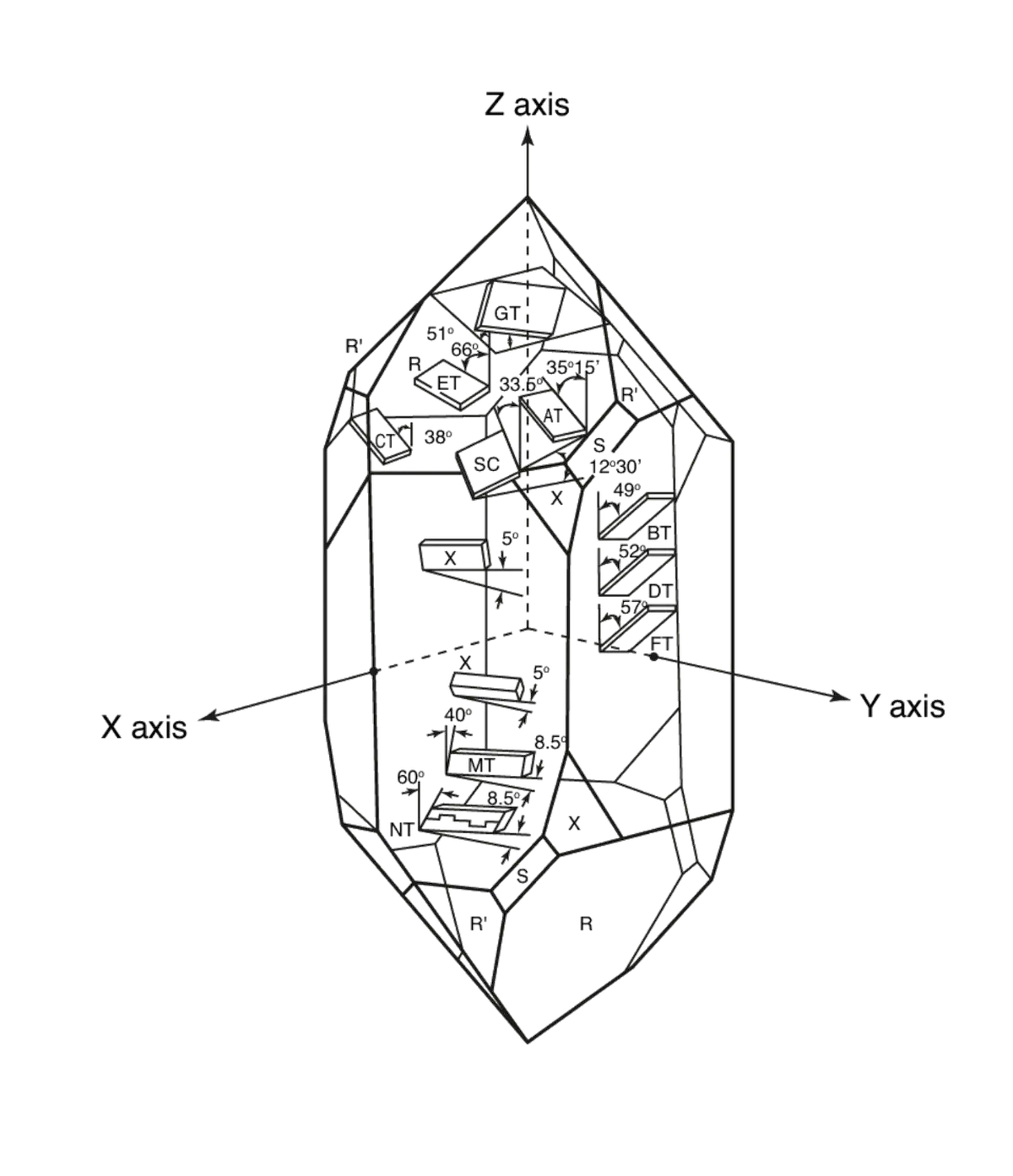
Our engineers work at the AT-cut and SC-cut level, controlling crystal orientation, thickness uniformity, and electrode geometry before a single package is sealed. Japanese vacuum-sealing equipment, ion-beam deposition systems, and vision-guided die-attach stations handle the precision steps that follow.

Comparison of AT-Cut and SC-Cut Quartz

Understanding the structural differences, manufacturing costs, and temperature curve behaviors of both crystal cuts.

AT-Cut Angle Alignment: Frequency-Temperature Curve Control

AT-cut crystals utilize adjustable cutting angles during processing. A minor cut deviation of just 2 arcminutes directly shifts the profile of the frequency-temperature curve.

A steep, narrow curve near room temperature supports standard indoor applications. In contrast, a flat curve across the -55°C to +105°C range satisfies the rigorous environmental demands of automotive and outdoor equipment. Each angle variation is selected to match a specific operating temperature window.

This precise angular alignment is systematically finalized prior to releasing a custom design to the production line.

SC-Cut: High Performance for Low Aging and Phase Noise

The SC-cut is a double-rotated crystal configuration. It requires complex manufacturing processes and carries higher production costs. This cut provides low aging rates and excellent close-in phase noise performance, which are essential for OCXO reference sources, radar systems, and precision instrumentation.

While the SC-cut has a limited frequency pulling range and is designed for specialized applications, it delivers precise stability. For a 10 MHz reference, this configuration maintains 2 ppb pk-pk across the full temperature range, with aging dropping below ±0.2 ppb/day after the first week of operation.

Five Dimensions. Every Project Starts Here.

Custom engineering projects are defined across five primary technical areas to ensure exact compatibility with target systems.

01

Frequency & Cut Type

32.768 kHz tuning forks to 220 MHz AT-cut fundamentals. SC-cut options for ovenized applications. Full engineering support for both standard and non-standard frequencies.

02

Performance

Jitter down to 0.05 ps typical (2520 package, 220 MHz differential output). Phase noise profiles can be tuned to target PLL bandwidths. Stability ranges from ±0.1 ppm (TCXO) to ±10 ppb (OCXO).

03

Temperature Range

Component qualification and delivery cover operating ranges from -55°C to +150°C. Performance is verified for automotive, outdoor infrastructure, and downhole environments.

04

Electrical Interface

Support for CMOS, clipped sine, LVDS, LVPECL, and HCSL interfaces. Supply voltages range from 1.8V to 5.0V. Available options include output enable, standby, and VCXO pull-range configurations.

05

Package & Footprint

Production-ready dimensions range from 12.0 × 10.0 mm down to 1.2 × 1.0 mm. Enclosures and pin configurations can be customized to match specific board layout layout requirements.

Standard Platforms Used for Custom Design

Custom projects are built on these six pre-tested platforms. This structure provides a reliable technical baseline that is then adjusted for specific application requirements.

Spread Spectrum

Spread-spectrum architectures that suppress clock harmonics at the source. Proven in helping a security display controller pass EMC without a PCB redesign.

High Temperature

Stable operation from -55°C to +150°C, with multi-point temperature compensation curves locked in at production.

High Precision

±0.1 ppm stability across temperature, built on SC-cut crystals with low-aging characteristics.

Low Jitter

From picosecond-level to 50 fs typical. Differential output across LVDS, LVPECL, and HCSL formats.

Structured Seven-Step Customization Process

Every custom project follows a defined path, with clear deliverables at each stage.

Prototype Validation MOQ: 1–2 Pieces

Initial engineering validation supports minimum order quantities of one to two units, facilitating functional prototype testing prior to high-volume production scaling.
01
Requirements Clarification (Day 1–2)
Technical assessment delivered within 24 hours based on application specs and target volume.
02
Documentation Package
Full provision of datasheets, RoHS/REACH compliance, quality certs, and PCN/EOL policies.
03
Samples & Engineering Support
Samples shipped within 48–72 hours, accompanied by direct engineer-to-engineer test setup and measurement guidance.
04
Customer Validation (EVT/DVT)
Prototype testing support backed by rapid root-cause failure analysis (FA) and corrective actions.
05
Validation (EVT/DVT)
Small-batch runs to verify process windows, lot-to-lot consistency, and packaging standards.
06
Mass Production
Finalization of AVL approval, delivery terms, and safety-stock mechanisms.
07
Lifecycle Management
Ongoing PCN execution, continuous cost optimization, and structured EOL planning.

Manufacturing, Quality, and Supply Chain Infrastructure

Production volume, quality inspection standards, and technical service timelines are defined by clear operational data.
3,000 m² facility, Japanese automated lines, 150M pcs/year capacity
Full-parameter outgoing inspection, lot traceability, AEC-Q200 qualified
12-month warranty, FA within 10–15 business days, global logistics

Contact Us Anytime

Drag & Drop Files, Choose Files to Upload

Starting a Custom Project

Contact Us Anytime

Drag & Drop Files, Choose Files to Upload