
FCom FSF-5050 series
220 & 221.6 MHz SAW Bandpass Filters
FSF-5050-220M / FSF-5050-221M6
Two frequency-specific options for VHF receivers and RF / IF signal selection. Choose the center frequency and passband definition that fit your receiver.
Model selection
Choose the required frequency and passband
Both models share the package and operating temperature range. Their loss definitions, bandwidth information and attenuation references differ.
FSF-5050-220M
220 MHz
220 MHz
Specified IL / ripple passband: 218–222 MHz
- 3 dB bandwidth
- Not specified
- Insertion loss
- 2.8 dB typ. / 4.2 dB max.
- Amplitude ripple
- 1.0 dB typ. / 2.2 dB max.
- Max RF input
- 10 dBm
FSF-5050-221M6
221.6 MHz
221.6 MHz
3 dB bandwidth: 7 MHz min. / 10 MHz typ. (referenced to ILmin)
- Minimum insertion loss (ILmin)
- 1.95 dB typ. / 3.0 dB max.
- Amplitude ripple
- 1.1 dB typ. / 2.2 dB max.
- Ripple evaluation interval
- 218.1–225.1 MHz
- Max RF input
- Confirm ordered variant
Keep the definitions separate. The 4 MHz specified interval for 220M is not a stated 3 dB bandwidth. For 221M6, 7 MHz is the minimum 3 dB bandwidth and 10 MHz is typical, not an upper limit. A shared package does not establish interchangeability.
Key electrical specifications
Key electrical specifications
Key values from each FCom datasheet. Use the corresponding PDF for complete attenuation data and test limits.
Scroll horizontally to view all columns.
FSF-5050-220M
FCom datasheet bundle, page 1 · 50 Ω source / load; stated I/O model: 50 Ω ∥ 0 pF
| Parameter | Min. | Typ. | Max. | Unit | Definition / condition |
|---|---|---|---|---|---|
| Center frequency | — | 220.0 | — | MHz | Datasheet center frequency |
| Specified passband | 218–222 (specified range) | MHz | Insertion loss and ripple interval | ||
| Insertion loss | — | 2.8 | 4.2 | dB | 218–222 MHz |
| Amplitude ripple | — | 1.0 | 2.2 | dB | 218–222 MHz |
| Operating temperature | −40 | — | +85 | °C | Operating range |
| Maximum input power | — | — | 10 | dBm | Maximum input rating |
FSF-5050-221M6
FCom datasheet bundle, page 2 · 50 Ω source / load; direct test connection
| Parameter | Min. | Typ. | Max. | Unit | Definition / condition |
|---|---|---|---|---|---|
| Center frequency | — | 221.6 | — | MHz | Midpoint of the 3 dB edges relative to ILmin |
| 3 dB bandwidth | 7 | 10 | — | MHz | Referenced to ILmin |
| Minimum insertion loss (ILmin) | — | 1.95 | 3.0 | dB | Minimum passband attenuation |
| Amplitude ripple | — | 1.1 | 2.2 | dB | 218.1–225.1 MHz |
| Ripple evaluation interval | 218.1–225.1 (specified range) | MHz | Interval for the ripple specification | ||
| Operating temperature | −40 | — | +85 | °C | Operating range |
“—” means no value is stated. The 221M6 ILmin value describes minimum passband attenuation; it is not a loss limit across the entire ripple interval.
Typical applications
Typical applications
01 / VHF RECEIVERS
Receiver band selection
Select the 220 or 221.6 MHz model to match the receiver frequency plan. Check the occupied signal band against the applicable loss, ripple and bandwidth definitions.
02 / RF FRONT ENDS
Signal selection
Provide bandpass filtering before subsequent receiver stages. Evaluate unwanted signals against the attenuation intervals and reference level in the selected model’s PDF.
03 / INTERMEDIATE FREQUENCY
Superheterodyne IF filtering
Use the selected filter in a receiver IF chain designed for its center frequency. Include insertion loss, passband shape and input conditions in the system review.
Integration notes
Integration notes
Use the model-specific test conditions
220M: 50 Ω source and load; the stated input/output model is 50 Ω in parallel with 0 pF.
221M6: direct test connection with 50 Ω source and load.
No external LC matching values are specified in these FCom sheets. Review the actual circuit impedances, fixture and PCB conditions during design-in.
Confirm ratings and reference levels
- 220M maximum input power: 10 dBm. For 221M6, confirm the ordered variant’s input power rating with FCom.
- Both models specify a 5 V maximum DC voltage and −40 to +85 °C storage temperature. The DC value is a limit, not a supply requirement.
- 220M attenuation is referenced to 0 dB; 221M6 attenuation and 3 dB bandwidth are referenced to ILmin.
- Keep RF traces short and connect ground and case-ground pads according to the FCom pin table.
Package & pin assignment
Package & pin assignment
The dimensions and pin assignments below apply to both models.
5.0 × 5.0 mm
8-pad SMD · 1.5 mm max height
Use the dimensioned drawing on the appropriate FCom PDF page to check mechanical fit and drawing orientation before assigning PCB pads.
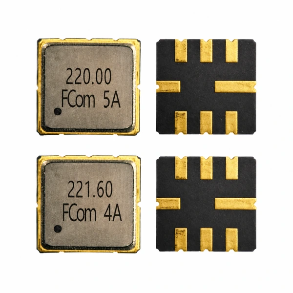
The product photographs show the front and underside for identification. Please contact FCom if a different pin configuration is required.
| Pin number | Function |
|---|---|
| 2 | Input / Output |
| 6 | Input / Output |
| 1, 3, 5, 7 | Ground |
| 4, 8 | Case Ground |
Selection and design-in support
Selection and design-in support
Share your receiver requirements with FCom to review the model and its application conditions.
Signal requirements
Center frequency, occupied bandwidth, loss budget, ripple and attenuation targets.
Interface and environment
Source / load conditions, RF input level, DC conditions and operating temperature.
Evaluation and ordering
Sample quantity, estimated annual usage, complete ordering code and confirmed variant ratings.
Engineering questions
Frequently asked questions
Can I compare 220M’s 4 MHz passband with 221M6’s 3 dB bandwidth?
These are different definitions. FSF-5050-220M specifies insertion loss and ripple over 218–222 MHz; its 3 dB bandwidth is not specified. FSF-5050-221M6 has a 3 dB bandwidth of 7 MHz minimum and 10 MHz typical, referenced to ILmin. Its ripple specification applies over 218.1–225.1 MHz.
How do insertion loss and ILmin differ on this page?
For FSF-5050-220M, the insertion-loss specification applies over 218–222 MHz. For FSF-5050-221M6, ILmin is the minimum attenuation within the passband. Its 1.95 dB typical and 3.0 dB maximum ILmin values are not a maximum-loss guarantee across the ripple interval.
Do the two models use the same attenuation reference?
No. FSF-5050-220M references stopband attenuation to 0 dB. FSF-5050-221M6 references stopband attenuation and its 3 dB bandwidth to ILmin. Use each model’s frequency intervals and reference definition when reviewing the complete PDF specifications.
What are the source, load and matching conditions?
FSF-5050-220M uses 50 Ω source and load test terminations with a stated input/output model of 50 Ω in parallel with 0 pF. FSF-5050-221M6 specifies a direct connection with 50 Ω source and load. The FCom sheets do not specify an external LC matching network. Confirm actual circuit impedances and PCB conditions during design-in.
What RF input power can FSF-5050-221M6 accept?
The FCom datasheet requires confirmation of the ordered variant’s input power rating. No numeric power limit is assigned to FSF-5050-221M6 on this page. Confirm the complete ordering code and RF input rating with FCom before finalizing the design.
What should I include in a product inquiry?
Include the selected model, required center frequency, occupied signal bandwidth, insertion-loss and ripple limits, attenuation targets, source/load conditions, RF input level and DC conditions, operating temperature, sample quantity and estimated annual usage. For FSF-5050-221M6, request confirmation of the ordered variant and its input power rating.