
FSF-5050 Series · IF Bandpass Filters
76.5 MHz IF SAW Filters
FSF-5050-76M5
Compare wideband, extended-temperature wideband and narrowband options for 76.5 MHz receiver IF filtering. Choose the bandwidth and temperature range required by your design.
Configuration selection
Choose the Passband and Temperature Range
Three selection options share the listed 5.0 × 5.0 mm package. Compare their bandwidths, temperature ranges, insertion loss and amplitude ripple.
Standard temperature
Wideband
12.7 MHz typ.
1 dB bandwidth · 12.0 MHz min.
- Temperature
- −40 to +85 °C
- Insertion loss
- 12.0 dB max.
For receiver paths requiring the wider listed passband and operation up to +85 °C.
Extended temperature
Wideband to +105 °C
12.7 MHz typ.
1 dB bandwidth · 12.0 MHz min.
- Temperature
- −40 to +105 °C
- Insertion loss
- 12.5 dB max.
The wider listed passband with extended temperature coverage and different maximum loss and ripple values.
Narrower passband
Narrowband
4.4 MHz typ.
1 dB bandwidth · 3.8 MHz min.
- Temperature
- −40 to +85 °C
- Insertion loss
- 12.0 dB max.
For receiver paths requiring the narrower listed passband and operation up to +85 °C.
The values above are for initial selection. Configuration names describe the options on this page; confirm the applicable specification and full ordering code with FCom. A shared package does not establish electrical interchangeability.
Electrical specifications
Compare the Reference Values
Reference values for initial selection. Confirm the applicable test limits, port impedance and matching conditions for the selected configuration. Typical values are not guaranteed limits.
Scroll horizontally to view all columns.
| Parameter | Wideband | Wideband to +105 °C | Narrowband |
|---|---|---|---|
| Center frequency, nominal | 76.500 MHz | 76.500 MHz | 76.500 MHz |
| 1 dB bandwidth | 12.0 MHz min. 12.7 MHz typ. |
12.0 MHz min. 12.7 MHz typ. |
3.8 MHz min. 4.4 MHz typ. |
| Insertion loss | 10.8 dB typ. 12.0 dB max. |
10.8 dB typ. 12.5 dB max. |
10.0 dB typ. 12.0 dB max. |
| Amplitude ripple | 0.6 dB p-p typ. 1.3 dB p-p max.fc ±6.0 MHz |
0.6 dB p-p typ. 1.4 dB p-p max.fc ±6.0 MHz |
0.7 dB p-p typ. 1.1 dB p-p max.fc ±1.9 MHz |
| Operating temperature | −40 to +85 °C | −40 to +105 °C | −40 to +85 °C |
| Port impedance | Confirm for selected configuration | Confirm for selected configuration | Confirm for selected configuration |
| Matching conditions | Confirm intended termination and matching | Confirm intended termination and matching | Confirm intended termination and matching |
All bandwidths use the stated 1 dB criterion. Ripple is specified over the frequency span shown for each configuration. The +105 °C option retains the standard wideband typical values and bandwidths; its listed maximum insertion loss and ripple differ.
Typical applications
Filtering in the Receiver IF Path
Select the filter configuration for the intended signal bandwidth and receiver operating conditions.
SDARS Receiver IF
76.5 MHz intermediate-frequency filtering for SDARS receiver chains, with passband selection based on the intended signal and receiver requirements.
High-IF Superheterodyne Receivers
Filtering after downconversion in receiver architectures using mixers and IF gain stages. Choose the passband and temperature option required by the design.
- LNA
- Mixer
- 76.5 MHz
IF SAW Filter - IF Gain / AGC
- ADC / DSP
Illustrative signal path only. Filter placement, gain distribution and interface conditions depend on the receiver design.
Integration notes
Confirm the Interface Before PCB Release
Confirm configuration-specific port impedance and matching conditions before finalizing the interface.
Source and Load Requirements
Provide the intended source and load requirements. Confirm port conditions before selecting a matching network or finalizing the interface.
Passband and Test Conditions
Review the 1 dB bandwidth and applicable ripple span together. Agree the relevant test limits and termination conditions for your selected configuration.
Board Evaluation
Verify pin orientation against the drawing, then evaluate the chosen filter with its intended termination and matching on the target PCB.
Package and pin assignment
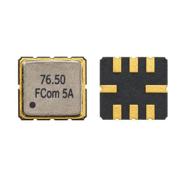
5.0 × 5.0 mm, Eight-Pad SMD Package
- Package outline
- 5.0 × 5.0 mm
- Maximum height
- 1.5 mm
- Terminations
- 8-pad, no-lead SMD
The drawing identifies the pin numbering in bottom view. Verify the orientation before layout; the package outline is not a separately specified PCB land pattern.
| Pin(s) | Function |
|---|---|
| 2 | Input/Output |
| 6 | Input/Output |
| 1, 3, 5, 7 | Ground |
| 4, 8 | Case Ground |
For alternative pin configurations, please contact FCom.
Working with FCom
Selection and Design-In Support
Configuration Review
Discuss your required passband, temperature range and receiver application to identify the appropriate selection option.
Interface Review
Clarify the source and load requirements and the port impedance and matching conditions relevant to the selected filter.
Documentation Review
Confirm the applicable specification, package drawing and ordering code. Ask about available response or test data for your evaluation.
Continue your selection
Engineering questions
Frequently Asked Questions
How do I choose between the wideband and narrowband configurations?
The wideband configuration lists a 1 dB bandwidth of 12.0 MHz minimum and 12.7 MHz typical. The narrowband configuration lists 3.8 MHz minimum and 4.4 MHz typical. Choose based on your signal bandwidth and receiver requirements, then confirm the applicable test limits.
What changes with the wideband option for +105 °C operation?
The extended-temperature wideband option covers −40 to +105 °C. Its listed maximum insertion loss is 12.5 dB and maximum amplitude ripple is 1.4 dB p-p. Typical values and bandwidths remain unchanged from the standard wideband option.
Can the filter connect directly to a 50 Ω signal path?
The listed information does not establish direct 50 Ω compatibility. Provide your intended source and load requirements so the port impedance and matching conditions can be reviewed before board evaluation.
Are the listed electrical values guaranteed production limits?
The listed values are references for initial selection. Confirm the applicable production specification and test conditions before ordering. Typical values are not guaranteed limits.
What package and pin assignment are shown?
The package measures 5.0 × 5.0 mm with a maximum height of 1.5 mm. Pins 2 and 6 are Input/Output, pins 1, 3, 5 and 7 are Ground, and pins 4 and 8 are Case Ground. Check the bottom-view orientation in the mechanical drawing.
How should I specify the required configuration in an inquiry?
Specify wideband, wideband to +105 °C or narrowband, together with the application, required bandwidth, source and load requirements, temperature range, sample quantity and estimated annual volume. These configuration names describe the selection options; confirm the full ordering code with FCom.