
FSF-5050 Series · IF SAW Bandpass Filters
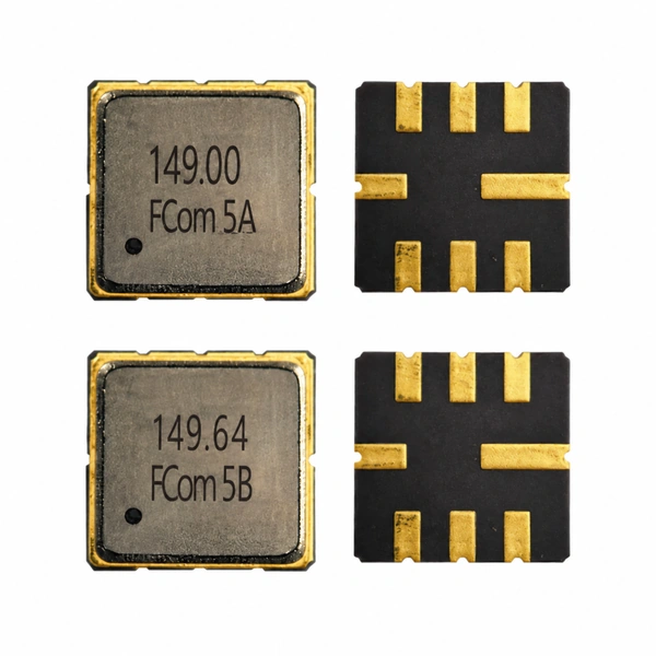
149.00 & 149.64 MHz SAW Filters
FSF-5050-149M · FSF-5050-149M64
Two IF filtering options for receiver and frequency-conversion designs. Select by the required passband and insertion-loss budget, then confirm the interface and PCB conditions.
Model selection
Choose the passband your IF chain needs
IF SAW Filter · 149.00 MHz
FSF-5050-149M
149.00 MHz
2 dB bandwidth: 2.0 MHz min. / 2.7 MHz typ.
- Insertion loss
- 2.0 dB typ. / 2.5 dB max.
- Amplitude ripple
- 1.5 dB typ. / 1.8 dB max. over fC ±1.0 MHz, −27.5 to +72.5 °C
- Operating temperature
- −40 to +85 °C
IF SAW Filter · 149.64 MHz
FSF-5050-149M64
149.64 MHz
Nominal bandwidth: 48 MHz (no dB criterion stated)
- Insertion loss
- 15.6 dB typ. / 17.0 dB max.
- Flatness
- 0.5 dB typ. / 0.7 dB max. over fC ±19.54 MHz, 25 °C
- Operating temperature
- −40 to +85 °C
Selection note: The bandwidth values use different definitions. Similar center frequencies and a shared package do not establish electrical interchangeability.
Electrical specifications
Model-specific limits and conditions
Keep the stated frequency intervals and temperature conditions with each parameter. Confirm the selected model’s test and matching conditions for your design.
Scroll horizontally to view all columns.
FSF-5050-149M · 149.00 MHz
| Parameter | Min. | Typ. | Max. | Unit | Condition / definition |
|---|---|---|---|---|---|
| Center frequency, fC | — | 149.00 | — | MHz | No Min./Max. classification stated |
| 2 dB bandwidth | 2.0 | 2.7 | — | MHz | 2 dB bandwidth definition |
| Insertion loss | — | 2.0 | 2.5 | dB | — |
| Amplitude ripple | — | 1.5 | 1.8 | dB p-p | fC ±1.0 MHz; −27.5 to +72.5 °C |
| Amplitude ripple | — | 2.0 | 2.2 | dB p-p | fC ±1.0 MHz; −40 to −27.5 °C and +72.5 to +85 °C |
| Operating temperature | −40 | — | +85 | °C | — |
“—” means the value or condition is not listed for that entry. The center frequency has no Min./Typ./Max. classification. Ripple limits are stated separately for two temperature intervals.
FSF-5050-149M64 · 149.64 MHz
| Parameter | Min. | Typ. | Max. | Unit | Condition / definition |
|---|---|---|---|---|---|
| Center frequency, fC | — | 149.64 | — | MHz | No Min./Max. classification stated |
| Nominal bandwidth | 48 (nominal) | MHz | No dB criterion stated | ||
| Insertion loss | — | 15.6 | 17.0 | dB | — |
| Flatness | — | 0.5 | 0.7 | dB p-p | fC ±19.54 MHz; 25 °C |
| Ripple | — | 0.6 | 1.2 | dB p-p | fC ±24.42 MHz |
| Operating temperature | −40 | — | +85 | °C | — |
“—” means the value or condition is not listed for that entry. The center frequency and nominal bandwidth have no Min./Typ./Max. classification. The 25 °C condition applies only to the flatness row; it is not a general test condition.
Typical applications
Filtering at the receiver IF stage
Receiver IF selection
Use the 149M in a 149 MHz IF path when its 2 dB passband meets the signal requirements. Check ripple across the intended temperature range.
Wideband downconversion
Evaluate the 149M64 after conversion to 149.64 MHz in a wideband receiver or SDR. Confirm the usable passband and gain budget.
RF / IF test equipment
Select the model that fits the instrument’s IF frequency and response requirements before downstream gain, digitization or signal processing.
Integration notes
Confirm the interface before PCB release
Source, load and matching
Source/load impedance and matching-network values are not specified in the available FCom data. Confirm these conditions for the selected model before treating either device as a direct connection or replacement.
Board evaluation
- Specify impedance and whether the signal path is single-ended or differential.
- Define the bandwidth criterion, acceptable ripple and insertion-loss budget.
- Verify response on the intended PCB with the agreed matching network and measurement reference planes.
Shared package
Package & pin assignment
5.0 × 5.0 mm
8-pad SMD · Height: 1.5 mm max.
Applies to the listed FCom configurations of both models. Confirm viewing direction and pad numbering against the selected model’s package information before layout release.
For alternative pin requirements, contact FCom.
| Pin | Function |
|---|---|
| 2 | Input / Output |
| 6 | Input / Output |
| 1, 3, 5, 7 | Ground |
| 4, 8 | Case Ground |
Selection and design-in support
Bring the IF requirements together
Share your target frequency, passband criterion, source/load requirements and operating temperature with FCom to discuss model selection. Include sample quantity and expected volume so the inquiry covers both evaluation and purchasing needs.
Engineering questions
Frequently asked questions
Are FSF-5050-149M and FSF-5050-149M64 interchangeable?
Do not assume interchangeability from the package size or similar center frequencies. The models have different bandwidth specifications and insertion-loss characteristics. Confirm the passband, gain budget, interface, pin orientation and PCB requirements for the selected model.
Can I compare 2.7 MHz and 48 MHz as the same bandwidth measurement?
No. The 2.7 MHz typical value for FSF-5050-149M is a 2 dB bandwidth. The 48 MHz value for FSF-5050-149M64 is nominal bandwidth with no attenuation-level definition stated in the FCom datasheet. Confirm the required passband criterion before selecting the wider-band model.
Does the 25 °C condition apply to all FSF-5050-149M64 specifications?
No. It is stated for the flatness row over fC ±19.54 MHz only. The ripple row over fC ±24.42 MHz does not separately state a measurement temperature. Both models list an operating range of −40 to +85 °C.
Can either filter connect directly to a 50 Ω signal path?
Direct connection is not established by the available FCom specifications. Confirm the source and load impedances, single-ended or differential interface, and matching conditions for the selected model before circuit evaluation.
Do both models have the same pin assignment?
The listed FCom configurations use pins 2 and 6 as Input/Output, pins 1, 3, 5 and 7 as Ground, and pins 4 and 8 as Case Ground. Verify the viewing direction and pad numbering before PCB release. Contact FCom for alternative pin requirements.
What information should I include in an inquiry?
Include the selected model or center frequency, required bandwidth and dB criterion, source and load requirements, operating temperature, application, sample quantity and estimated annual volume.