
FSF-5050 Series · SAW Bandpass Filter
713 MHz SAW Bandpass Filter
FSF-5050-713M
A 5.0 × 5.0 mm SMD SAW filter with a specified 710–716 MHz passband for UHF receiver and test equipment designs.
Key Features
Define the Passband and Interface
Specified Passband
710–716 MHz
Specified passband with a 6 MHz span. This is not a 3 dB bandwidth specification.
Insertion Loss
2.4 dB typ.
4.5 dB maximum over 710–716 MHz at the 25 °C reference temperature.
Amplitude Ripple
0.5 dB typ.
Over 710–716 MHz. Maximum not separately stated in the supplied table.
The specified passband 710–716 MHz is a frequency range, not the 3 dB bandwidth. A 3 dB bandwidth is not specified in the supplied datasheet.
Electrical Specifications
Six Key Selection Parameters
Reference temperature for electrical performance: 25 °C. The test setup uses a 50 Ω source and load, directly connected as shown in the reference circuit. These source and load values do not specify the device input or output impedance.
Scroll horizontally to view all columns.
| Parameter | Min. | Typ. | Max. | Unit | Definition / condition |
|---|---|---|---|---|---|
| Center frequency | — | 713.0 | — | MHz | Reference: 25 °C |
| Specified passband | — | — | — | MHz | 710–716 MHz; span 6 MHz |
| Insertion loss | — | 2.4 | 4.5 | dB | Over 710–716 MHz; reference: 25 °C |
| Amplitude ripple | — | 0.5 | — | dB | Over 710–716 MHz; reference: 25 °C; maximum not separately stated |
| 3 dB bandwidth | — | — | — | MHz | Not specified |
| Operating temperature | −10 | — | +60 | °C | Operating range; not an electrical test condition |
| Storage temperature | −40 | — | +85 | °C | Storage range |
— means not specified, not zero. The passband row gives a frequency range, not Min./Typ./Max. limits. Its 6 MHz span is not a specified 3 dB bandwidth; no 3 dB bandwidth value is provided. The 0.5 dB ripple is a typical value; no maximum is specified. The operating and storage ranges are separate from the 25 °C electrical reference condition. Typical values are for design guidance. Refer to the FCom datasheet and confirm applicable production limits with FCom.
Typical Applications
Band Selection from 710 to 716 MHz
UHF Receiver Filtering
Evaluate the specified 710–716 MHz passband for signal selection in a UHF receiver. Compare insertion loss and the typical ripple with the requirements of your occupied signal band.
Receiver Preselector
Consider the filter for frequency selection ahead of a receiver stage. Validate system rejection, insertion loss and signal levels with the intended source and load.
Measurement-Path Filtering
Consider the filter for a measurement path centered on 713 MHz where selection across 710–716 MHz is required. Validate the complete fixture and measurement conditions.
Integration Notes
Match the Evaluation Conditions
Test Setup and Device Impedance
The reference test circuit directly connects the filter to a 50 Ω source and load. No external matching network is shown for this test setup. Evaluate your actual source, load and PCB parasitics; the test setup is not a statement of the device impedance.
Complete Signal Path
Insertion loss and amplitude ripple are specified over 710–716 MHz at the 25 °C reference temperature. Ripple is typical only. Evaluate performance over the required operating temperature range; do not assume the reference-temperature values are guaranteed across −10 to +60 °C.
Package & Pin Assignment
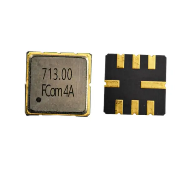
5 × 5 mm, 8-Terminal SMD Package
The FCom drawing specifies a 5.0 × 5.0 mm body and a maximum height of 1.5 mm. The pin assignments at right apply to FSF-5050-713M.
- Body dimensions
- 5.0 × 5.0 mm
- Maximum height
- 1.5 mm
- Package type
- 8-SMD, no lead
Use the dimension drawing in the FCom datasheet for mechanical review. Its plan-view orientation is not explicitly labeled; confirm orientation and the PCB land pattern before layout release. Contact FCom for other pin configurations.
| Pin(s) | Function |
|---|---|
| 2 | Input |
| 6 | Output |
| 1, 3, 5, 7 | Ground |
| 4, 8 | Case ground |
Selection and Design-In Support
Make the Design Requirements Clear
For selection and design-in discussions, provide the required bandwidth and its definition, source and load requirements, operating temperature, sample quantity and expected usage. Reference FSF-5050-713M and confirm the complete ordering code and applicable production specification with FCom.
The model designation alone is not a confirmed complete ordering code.
Engineering Questions
Frequently Asked Questions
Is 6 MHz the 3 dB bandwidth?
No. 6 MHz is the span of the specified 710–716 MHz passband. Neither the supplied FCom datasheet nor the reference specification provides a numerical 3 dB bandwidth. Do not use the passband endpoints as 3 dB cutoff frequencies.
Where do the insertion-loss and ripple values apply?
They apply over 710–716 MHz at a reference temperature of 25 °C. Insertion loss is 2.4 dB typical and 4.5 dB maximum. Amplitude ripple is 0.5 dB typical; no maximum ripple value is specified.
Does the 50 Ω test setup specify the device impedance?
No. The reference circuit directly connects the filter to a 50 Ω source and a 50 Ω load. These are test conditions. Device input and output impedances are not specified, so evaluate the filter with your actual source, load and PCB layout.
How do the reference, operating and storage temperatures differ?
25 °C is the reference temperature for the electrical specifications. The operating range is −10 to +60 °C; the storage range is −40 to +85 °C. The storage range is not an operating rating, and the reference-temperature electrical values should not be treated as guaranteed full-temperature limits.
How should the ground pins be connected?
The FCom datasheet assigns pin 2 to input and pin 6 to output. Pins 1, 3, 5 and 7 are ground; pins 4 and 8 are case ground. Confirm the drawing orientation and land pattern before PCB release.
What information should I include in a design-in inquiry?
Include FSF-5050-713M, the required signal band and bandwidth definition, loss and ripple requirements, source and load requirements, operating temperature, sample quantity and expected usage. Confirm the complete ordering code and applicable production limits with FCom before ordering.