
FSF-5050 Series · SAW Bandpass Filter
584 MHz SAW Bandpass Filter
FSF-5050-584M
RF/IF signal selection across a specified 578–590 MHz passband in a 5.0 × 5.0 mm, 8-pad SMD package. Typical insertion loss is 1.6 dB, with a 4.5 dB maximum over the specified passband.
Key Features
Key Selection Points
Specified Passband
578–590 MHz
Insertion loss and amplitude ripple are specified across this interval. The 3 dB bandwidth is not provided.
Passband Ripple
0.7 dB typ.
2.0 dB maximum amplitude ripple across 578–590 MHz.
Test Terminations
50 Ω / 50 Ω
Source / load test conditions. Device input and output impedances are not specified.
The specified passband 578–590 MHz is a frequency range, not the 3 dB bandwidth. A 3 dB bandwidth is not specified in the supplied datasheet.
Electrical Specifications
Six Key Selection Parameters
Key values for FSF-5050-584M from the supplied FCom datasheet. Typical values are for design guidance; confirm applicable production limits before design release.
Scroll horizontally to view all columns.
| Parameter | Min. | Typ. | Max. | Unit | Definition / condition |
|---|---|---|---|---|---|
| Center frequency | — | 584 | — | MHz | Typical value |
| Specified passband | — | — | — | MHz | 578–590 MHz; not a 3 dB bandwidth |
| Insertion loss | — | 1.6 | 4.5 | dB | Over 578–590 MHz |
| Amplitude ripple | — | 0.7 | 2.0 | dB | Over 578–590 MHz |
| 3 dB bandwidth | — | — | — | MHz | Not specified |
| Operating temperature | −20 | — | +75 | °C | Operating limits; measurement temperature not stated |
— means not specified or not applicable in that column; it does not mean zero. The supplied FCom table does not state a measurement temperature. Storage temperature: −40 °C to +85 °C. The specified 578–590 MHz interval must not be described as a 12 MHz 3 dB bandwidth. Refer to the FCom datasheet for the supplied specification and package detail.
Typical Applications
RF/IF Signal Selection Around 584 MHz
584 MHz RF/IF Receivers
Passband selection in receiver stages operating around 584 MHz, subject to the required loss and ripple budget.
UHF Receiver Front Ends
Frequency-selective filtering for wanted signals in the specified passband. Check system-level rejection and interface requirements during evaluation.
Test and Measurement
Band selection in measurement signal chains that use the 578–590 MHz interval. Evaluate the filter within the intended measurement setup.
Integration Notes
Reproduce the Relevant Test Conditions
Source and Load
The reference measurement uses a single-ended source and load, each terminated in 50 Ω. These are test conditions and do not establish the device’s own input or output impedance.
Matching and Layout
Assess the required matching with the actual source, load and PCB parasitics; no matching-component values are provided in the FCom attachment.
Frequency and Temperature Evaluation
Verify performance across the intended operating temperature and frequency range. The same center frequency alone does not establish drop-in compatibility.
Release Checks
Confirm passband definition, insertion loss and ripple limits, interface and pin assignment, package height and the required operating temperature before qualification.
Package & Pin Assignment
5 × 5 mm, 8-Pad SMD Package
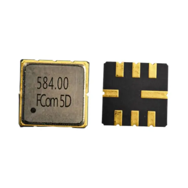
The supplied FCom drawing specifies a maximum height of 1.5 mm. The product photograph shows the marked lid and the eight-pad underside.
- Body dimensions
- 5.0 × 5.0 mm
- Maximum height
- 1.5 mm
- Package type
- 8-SMD, no lead
Use the mechanical drawing in the FCom datasheet to confirm dimensions and pad orientation before layout release. The photograph is not a footprint drawing. Contact FCom for other pin configurations.
| Pad(s) | Function |
|---|---|
| 2 | Input/Output |
| 6 | Input/Output |
| 1, 3, 5, 7 | Ground |
| 4, 8 | Case ground |
Selection and Design-In Support
Define the Passband, Loss and Interface Together
Discuss FSF-5050-584M with FCom using your required passband, bandwidth definition, source and load requirements, temperature range, sample quantity and estimated usage. Include any package or pin constraints to support a meaningful compatibility review.
FSF-5050-584M is the model designation shown in the supplied datasheet. Confirm the complete ordering code before placing an order.
Engineering Questions
Frequently Asked Questions
Is 578–590 MHz the 3 dB bandwidth?
No. It is the specified passband used for insertion loss and amplitude ripple. A 3 dB bandwidth is not specified in the supplied FCom datasheet.
Does the 50 Ω test setup define the device impedance?
No. The source and load are each terminated in 50 Ω for testing. Device input and output impedances are not specified; assess matching with the intended RF interface.
Which pads carry the signal?
The FCom pin table identifies pads 2 and 6 as Input/Output, pads 1, 3, 5 and 7 as ground, and pads 4 and 8 as case ground. Confirm footprint orientation against the applicable mechanical drawing before layout release.
What temperature range applies?
The specified operating range is −20 °C to +75 °C. Storage is specified separately as −40 °C to +85 °C. The supplied FCom table does not state a measurement temperature.
Can this model directly replace another 584 MHz filter?
Frequency alone does not establish interchangeability. Compare the passband definition, loss and ripple limits, interface and matching, pin assignment, package height and operating temperature before qualification.
What should I include in a technical inquiry?
Include FSF-5050-584M, the required passband and bandwidth definition, source and load requirements, operating temperature, sample quantity and estimated usage. Confirm the complete ordering code with FCom before ordering.