
FSF-5050 Series · RF/IF Signal Selection
352 MHz SAW Bandpass Filter
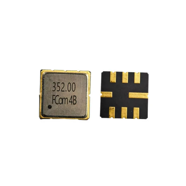
FSF-5050-352M
A compact SAW filter for signal selection near 352 MHz, with 1.0 MHz typical 3 dB bandwidth and operation from −40 to +85 °C. Evaluate its passband and loss budget for your RF or compatible IF path.
Key features
Select Around the Required Signal Band
Typical 3 dB Bandwidth
1.0 MHz typ.
Listed in the FCom datasheet for initial selection. Confirm the bandwidth limits required by your signal.
Insertion Loss
3.6 dB max.
The reference specification applies the loss limit over 351.5–352.5 MHz. Include this loss in the receiver budget.
Operating Range
−40 to +85 °C
Review signal coverage and filter response across the application’s operating temperature range.
The 351.5–352.5 MHz loss and ripple interval and the 1.0 MHz typical 3 dB bandwidth are separate specifications. The 1.0 MHz value is typical and is not a guaranteed minimum.
Electrical specifications
Six Key Parameters for Design Review
Values below apply to FSF-5050-352M. Typical values are design guidance; confirm the applicable production limits and test conditions before ordering.
Scroll horizontally to view all columns.
| Parameter | Min. | Typ. | Max. | Unit | Definition / condition |
|---|---|---|---|---|---|
| Center frequency, fc | — | 352.0 | — | MHz | Nominal/typical from FCom datasheet |
| 3 dB bandwidth | — | 1.0 | — | MHz | Typical value; no min./max. specified |
| Insertion loss | — | 1.9 | 3.6 | dB | 351.5–352.5 MHz in the reference specification |
| Amplitude ripple | — | 0.2 | 2.1 | dB | 351.5–352.5 MHz |
| Operating temperature | −40 | — | +85 | °C | Operating range |
| Input / output impedance | — | — | — | Ω | Not specified in the FCom datasheet |
“—” means not specified, not zero. Electrical measurement temperature is not stated. The 351.5–352.5 MHz loss/ripple interval and the 1.0 MHz typical 3 dB bandwidth are separate specifications.
Typical applications
Filtering in RF and Compatible IF Paths
Land-Mobile Radio
Evaluate for signal selection near 352 MHz in licensed land-mobile or public-safety radio designs. Confirm the assigned frequencies and required rejection mask.
IF / Channel Selection
Use in an IF path when the 352 MHz center frequency and required signal bandwidth fit the receiver architecture.
Wireless Modules
Consider for band selection in wireless communication modules. Check insertion loss, ripple and interfering signals against the system budget.
This is a filter centered at 352 MHz. It does not provide a continuous 350–370 MHz passband.
Integration notes
Check the Interface Before PCB Release
Reference Test Interface
The reference measurement circuit uses 50 Ω source and load terminations, with direct connections and no external matching components shown. These are test conditions, not specified device impedances.
Grounding and Layout
The reference circuit uses pin 2 for input and pin 6 for output, with pins 1, 3, 4, 5, 7 and 8 grounded. Verify orientation against the applicable FCom drawing.
Rejection Requirements
Provide the interfering frequencies and required attenuation limits. Confirm the applicable FCom rejection specification rather than inferring it from bandwidth alone.
Evaluate the response with the intended source, load, PCB and operating temperature. The reference test connection does not establish performance on every board.
Mechanical integration
5.0 × 5.0 mm, Eight-Pad SMD Package
Package & Pin Assignment
The FCom datasheet identifies pins 2 and 6 as Input/Output. The table here reproduces its pin functions for FSF-5050-352M.
Confirm maximum height before layout release. The FCom drawing specifies 1.5 mm maximum; the reference outline specifies 1.7 mm maximum. Confirm the applicable package drawing, height and land pattern with FCom.
For other pin requirements, contact FCom. Do not infer compatibility with another frequency option from package appearance alone.
| Pin | Function |
|---|---|
| 2 | Input/Output |
| 6 | Input/Output |
| 1, 3, 5, 7 | Ground |
| 4, 8 | Case ground |
Selection and design-in support
Define the Passband and System Requirements
Include FSF-5050-352M, your application, required center frequency, bandwidth definition, source/load requirements, temperature range and rejection targets in a technical inquiry. Add sample quantity and estimated annual volume.
Confirm the applicable electrical limits, mechanical drawing and complete ordering code with FCom before design release.
Related frequency selection
Engineering questions
Frequently Asked Questions
Is the 1.0 MHz bandwidth a guaranteed minimum?
No. The FCom datasheet lists 1.0 MHz as a typical 3 dB bandwidth, with no minimum or maximum stated. The reference loss and ripple interval of 351.5–352.5 MHz is a separate specification and does not establish a guaranteed 3 dB bandwidth.
Can I connect the filter directly to a 50 Ω signal path?
The reference test circuit uses 50 Ω source and load terminations without external matching components. The FCom datasheet does not specify the device input/output impedances. Verify the response with the intended source, load and PCB before design release.
Does this filter cover the entire 350–370 MHz band?
No. FSF-5050-352M is centered at 352 MHz. Evaluate its specified response against your actual signal bandwidth and assigned operating frequencies; the broader application band is not the filter passband.
Which package height should be used for the design?
The FCom drawing shows 1.5 mm maximum height, while the reference outline shows 1.7 mm maximum. Confirm the applicable FCom mechanical drawing, maximum height, pin orientation and land pattern before releasing the PCB or enclosure.
What information should I provide for selection support?
Provide FSF-5050-352M, the application, required center frequency, bandwidth and its definition, source/load requirements, operating temperature, rejection targets, sample quantity and estimated annual volume. Confirm the complete ordering code and production limits with FCom.