
FCom Fuji Crystal · FSF-5050 Series
340 & 345 MHz SAW Bandpass Filters
FSF-5050-340M · FSF-5050-345M
Two receiver-filtering options with distinct passbands and operating temperature ranges.
Select the 337–343 MHz passband for 340 MHz RF / IF filtering, or the 344.6–345.4 MHz passband for 345 MHz receiver filtering.
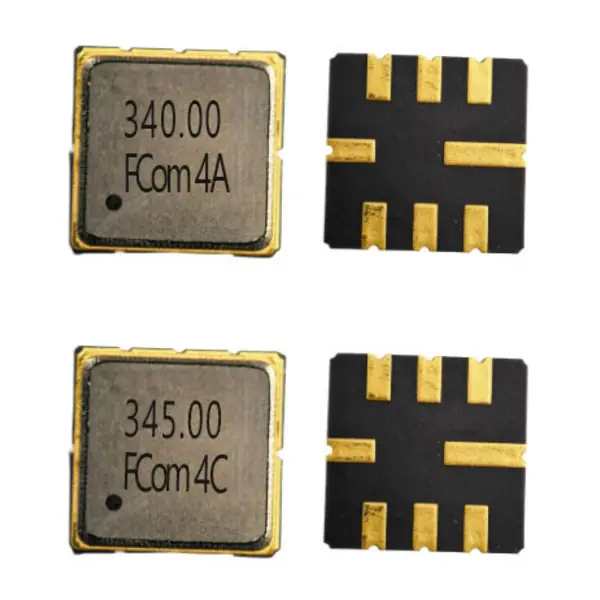
Marked lids on the left; pad-side views on the right.
Model Selection
Choose the passband and temperature range
Specified passband · 337–343 MHz
FSF-5050-340M
340 MHz
Specified passband 337–343 MHz · 6.0 MHz span, not a 3 dB bandwidth
- Insertion loss
- 1.9 dB typ. / 3.5 dB max. over 337–343 MHz
- Amplitude ripple
- 0.4 dB typ. / 1.5 dB max. over 337–343 MHz
- Operating range
- −10 to +65 °C
- Source / load test
- 50 Ω / 50 Ω
For RF / IF paths requiring the specified 337–343 MHz passband. Check the narrower operating temperature range against the application.
Specified passband · 344.6–345.4 MHz
FSF-5050-345M
345 MHz
Specified passband 344.6–345.4 MHz · 0.8 MHz span, not a 3 dB bandwidth
- Insertion loss
- 2.3 dB typ. / 3.3 dB max. over 344.6–345.4 MHz
- Amplitude ripple
- 0.4 dB typ. / 1.3 dB max. over 344.6–345.4 MHz
- Operating range
- −25 to +85 °C
- Source / load test
- 50 Ω / 50 Ω
For 345 MHz receiver paths requiring the specified 344.6–345.4 MHz passband. Review the rejection limits at the relevant interference frequencies.
Both options use the listed FCom 5.0 × 5.0 mm package. Their frequencies, passbands and temperature limits differ; the shared package does not establish interchangeability.
Electrical Specifications
Model-specific values and conditions
Each table lists six key specifications. “—” means the value is not specified; it does not mean zero. Typical values are for design guidance. Refer to the FCom datasheet for the complete attenuation ranges and other parameters.
FSF-5050-340M
Scroll horizontally to view all columns.
| Parameter | Min. | Typ. | Max. | Unit | Definition / condition |
|---|---|---|---|---|---|
| Center frequency | — | 340.0 | — | MHz | fC |
| Specified passband | — | — | — | MHz | 337–343; IL / ripple interval; not a 3 dB bandwidth |
| Insertion loss | — | 1.9 | 3.5 | dB | Over 337–343 MHz |
| Amplitude ripple | — | 0.4 | 1.5 | dB | Over 337–343 MHz |
| Absolute attenuation | 40 | 46 | — | dB | 300–320 MHz; 0 dB reference |
| Operating temperature | −10 | — | +65 | °C | Operating limits |
Specified passband is a frequency interval, not a Min. / Typ. / Max. bandwidth entry. A 3 dB bandwidth and a general measurement temperature are not stated. The selected attenuation row does not describe the entire stopband. Return loss is −14 dB typ. / −9 dB max. over 337–343 MHz; the signed values follow the FCom datasheet. Maximum input power is 10 dBm; maximum DC voltage is 3 V; storage temperature is −40 to +85 °C.
FSF-5050-345M
Scroll horizontally to view all columns.
| Parameter | Min. | Typ. | Max. | Unit | Definition / condition |
|---|---|---|---|---|---|
| Center frequency | — | 345.0 | — | MHz | fC |
| Specified passband | — | — | — | MHz | 344.6–345.4; IL / ripple interval; not a 3 dB bandwidth |
| Insertion loss | — | 2.3 | 3.3 | dB | Over 344.6–345.4 MHz |
| Amplitude ripple | — | 0.4 | 1.3 | dB | Over 344.6–345.4 MHz |
| Absolute attenuation | 50 | 60 | — | dB | 10–320 MHz; 0 dB reference |
| Operating temperature | −25 | — | +85 | °C | Operating limits |
Specified passband is a frequency interval, not a Min. / Typ. / Max. bandwidth entry. A 3 dB bandwidth and a general measurement temperature are not stated. The selected attenuation row does not describe the entire stopband. Maximum input power is 10 dBm; maximum DC voltage is 3 V; storage temperature is −40 to +85 °C. Follow ESD handling precautions. The wider operating range of 345M must not be applied to 340M.
Confirm the applicable FCom production limits and complete ordering code before design release. Refer to the FCom datasheet for the full attenuation bands and additional maximum ratings.
Typical Applications
Filtering in the receiver signal path
340 MHz RF / IF channel selection
Use FSF-5050-340M for signal filtering over 337–343 MHz in a receiver RF or IF path. Assess out-of-band suppression using the frequency intervals specified for this model.
345 MHz short-range control receivers
Evaluate FSF-5050-345M for front-end filtering and channel selection over 344.6–345.4 MHz. Review its operating temperature and attenuation limits against the receiver requirements.
Integration Notes
Review the interface before PCB release
Source, load and matching
Both models are documented with 50 Ω source and load reference circuits using direct connection without external L/C matching.
These are reference termination conditions. Device input and output impedances are not independently specified in the supplied FCom datasheet. Evaluate the selected part with the intended source, load and PCB layout.
Confirm the applicable FCom pin assignment. A third-party part with a similar response may use different signal terminals.
Ratings and measurement conventions
Both models list maximum input power of 10 dBm, maximum DC voltage of 3 V and storage temperature of −40 to +85 °C. These maximum ratings are not recommended operating targets.
340M: the signed return-loss entry is −14 dB typ. / −9 dB max. over 337–343 MHz. The signs follow the FCom datasheet; confirm the reporting convention for acceptance testing.
345M: follow ESD handling precautions. Its wider operating temperature range must not be applied to 340M.
Shared FCom Package
Package & Pin Assignment
The supplied FCom drawings specify a maximum height of 1.5 mm for both FSF-5050-340M and FSF-5050-345M.
5.0 × 5.0 mm · 8-pad SMD
The pin functions shown here apply to these FCom configurations. Confirm the viewing direction, pad numbering and PCB land pattern against the applicable drawing before layout release. The product photograph is not a placement drawing.
Do not substitute a third-party drawing based only on frequency or package name. Contact FCom for alternative pin requirements.
| Pin(s) | Function |
|---|---|
| 2 | Input / Output |
| 6 | Input / Output |
| 1, 3, 5, 7 | Ground |
| 4, 8 | Case ground |
Selection and Design-In Support
What to include in your inquiry
Share your frequency, required passband or bandwidth criterion, source and load requirements, operating temperature and application. Include sample quantity and estimated usage, then confirm the applicable specification and complete ordering code with FCom.
Engineering Questions
Frequently Asked Questions
How do I choose between the 340 MHz and 345 MHz models?
Choose the center frequency and specified passband required by the signal path. FSF-5050-340M specifies 337–343 MHz and operation from −10 to +65 °C. FSF-5050-345M specifies 344.6–345.4 MHz and operation from −25 to +85 °C. Check the model-specific loss, ripple and rejection requirements before selection.
Are the 6.0 MHz and 0.8 MHz spans 3 dB bandwidths?
No. They are the spans of the specified insertion-loss and ripple passbands: 337–343 MHz for 340M and 344.6–345.4 MHz for 345M. A 3 dB bandwidth is not specified for either model in the supplied FCom datasheet.
Can I evaluate these filters in a 50 Ω signal path?
The supplied FCom documentation describes 50 Ω source and load reference circuits with direct connection and no external L/C matching. This does not independently specify each device’s input and output impedances. Verify the selected model with the intended source, load and PCB layout.
Does a shared package mean the filters are interchangeable?
No. The two FCom models share the listed package and pin functions but have different center frequencies, passbands and operating temperature ranges. Third-party parts with similar electrical values may also have different signal pins, pad layouts or heights. Confirm the applicable FCom drawing before layout release.
Why is the 340M return-loss entry negative?
The supplied FCom datasheet retains the signed source values: −14 dB typical and −9 dB maximum over 337–343 MHz. Treat these as the signed entry shown in the source, rather than silently converting them into positive return-loss limits. Confirm the required convention when specifying an acceptance test.
What should I include in a technical inquiry?
Include the selected model or center frequency, required passband or bandwidth criterion, source and load requirements, operating temperature, application, sample quantity and estimated usage. Confirm the complete ordering code and applicable specification with FCom before ordering.