
FCom Fuji Crystal · FSF-5050
309, 315 & 319.5 MHz SAW Bandpass Filters
FSF-5050-309M · FSF-5050-315M · FSF-5050-319M5
Three frequency options for receiver filtering in a 5.0 × 5.0 mm, 8-pad SMD package.
Choose by center frequency, bandwidth definition and matching requirements. All three models specify an operating temperature range of −40 to +85 °C.
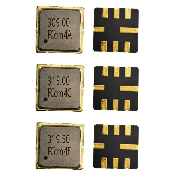
Left: marked lids. Right: pad-side views.
Model Selection
Choose your frequency
The same package size does not establish electrical interchangeability. Compare each model using its stated bandwidth definition and test or matching conditions.
Specified passband · 304.225–314.285 MHz
FSF-5050-309M
309 MHz
Specified passband 304.225–314.285 MHz · 10.060 MHz span, not a 3 dB bandwidth
- Insertion loss
- 1.9 dB typ. / 3.0 dB max. over 304.225–314.285 MHz
- Amplitude ripple
- 0.8 dB typ. / 2.0 dB max. over 304.225–314.285 MHz
- Absolute attenuation
- 40 dB min. / 45 dB typ. (50–280 MHz)
- Operating range
- −40 to +85 °C
IL and ripple apply over the specified passband. Reference test uses 50 Ω source and load with direct connection.
3 dB bandwidth · 0.6 MHz typ.
FSF-5050-315M
315 MHz
3 dB bandwidth 0.6 MHz typ. — original FCom value, external validation pending
- Insertion loss
- 3.0 dB typ. / 5.5 dB max.
- Input / output impedance
- Not supplied
- Operating range
- −40 to +85 °C
- Verification
- External reference is an update notice only
Original FCom values; external validation pending. No passband, ripple, attenuation or matching conditions are inferred.
3 dB bandwidth · 0.5 / 0.6 / 0.8 MHz
FSF-5050-319M5
319.5 MHz
3 dB bandwidth 0.5 MHz min. / 0.6 MHz typ. / 0.8 MHz max.
- Center frequency
- 319.42 / 319.5 / 319.58 MHz (min. / typ. / max.)
- Minimum insertion loss
- 2.2 dB typ. / 2.8 dB max. (ILmin)
- Relative attenuation
- 40 dB min. / 50 dB typ. at Fc − 10.7 MHz and Fc − 21.4 MHz
- Operating range
- −40 to +85 °C
Reference test uses 50 Ω source and load with a series 82 nH inductor at each signal port. Reference terminal mapping to FCom pins requires confirmation.
The 309 MHz model specifies an insertion-loss and ripple passband; the 315 MHz and 319.5 MHz models specify 3 dB bandwidth. These are different definitions and do not establish interchangeability.
Electrical Specifications
Model-specific values and conditions
“—” means no value is specified; it does not mean zero. Typical values are for design guidance. The supplied FCom datasheet contains the remaining parameters and mechanical information.
FSF-5050-309M
Scroll horizontally to view all columns.
| Parameter | Min. | Typ. | Max. | Unit | Definition / condition |
|---|---|---|---|---|---|
| Center frequency | — | 309.0 | — | MHz | fC |
| Insertion loss | — | 1.9 | 3.0 | dB | Over 304.225–314.285 MHz |
| Specified passband | — | — | — | MHz | 304.225–314.285; IL / ripple interval; not a 3 dB bandwidth |
| Amplitude ripple | — | 0.8 | 2.0 | dB | Over 304.225–314.285 MHz |
| Absolute attenuation (0 dB reference) | 40 | 45 | — | dB | 50–280 MHz |
| Absolute attenuation (0 dB reference) | 30 | 34 | — | dB | 350–700 MHz |
Operating temperature: −40 to +85 °C. Storage temperature: −40 to +85 °C. Maximum input power: 10 dBm. Maximum DC voltage: 5 V. Passband span: 10.060 MHz; this is not a specified 3 dB bandwidth. Reference measurement uses 50 Ω source and load with direct connection. Device input and output impedances are not specified. Follow appropriate ESD handling.
FSF-5050-315M
Scroll horizontally to view all columns.
| Parameter | Min. | Typ. | Max. | Unit | Definition / condition |
|---|---|---|---|---|---|
| Center frequency | — | 315.0 | — | MHz | Original FCom value |
| Insertion loss | — | 3.0 | 5.5 | dB | Original; test conditions not supplied |
| 3 dB bandwidth | — | 0.6 | — | MHz | Original FCom value |
| Operating temperature | −40 | — | +85 | °C | Original FCom limits |
| Input impedance | — | — | — | — | Not supplied |
| Output impedance | — | — | — | — | Not supplied |
External reference validation pending. The external document contains an update notice only. Confirm the retained original FCom values and matching conditions before design-in; no passband, ripple or attenuation limits are inferred.
FSF-5050-319M5
Scroll horizontally to view all columns.
| Parameter | Min. | Typ. | Max. | Unit | Definition / condition |
|---|---|---|---|---|---|
| Center frequency | 319.42 | 319.5 | 319.58 | MHz | fC |
| Minimum insertion loss | — | 2.2 | 2.8 | dB | ILmin |
| 3 dB bandwidth | 0.5 | 0.6 | 0.8 | MHz | BW3 |
| Relative attenuation | 40 | 50 | — | dB | fC − 10.7 MHz; relative to ILmin |
| Relative attenuation | 40 | 50 | — | dB | fC − 21.4 MHz; relative to ILmin |
| Operating temperature | −40 | — | +85 | °C | Operating limits |
Reference measurement: 50 Ω source and load with a series 82 nH inductor at each signal port. Input port device impedance: 3.97 kΩ ∥ 4.37 pF. Output port device impedance: 2.56 kΩ ∥ 4.27 pF. Reference terminal mapping to FCom pins requires confirmation. A fixed passband and amplitude-ripple limits are not specified. Storage temperature: −40 to +85 °C. Maximum input power: 10 dBm. Maximum DC voltage: 12 V. MSL 1. Follow appropriate ESD handling.
Refer to the FCom datasheet for the complete attenuation ranges, mechanical drawings and any additional maximum ratings. Confirm the applicable FCom production limits and complete ordering code before design release.
Typical Applications
Filtering in the receiver signal path
309 MHz receiver preselection
Filter the receiver signal over the specified 304.225–314.285 MHz passband and suppress signals in the documented out-of-band regions.
315 MHz remote-control receivers
Evaluate the 315 MHz option for receiver front-end filtering and short-range channel selection. Confirm the retained specifications before design-in.
319.5 MHz narrowband receivers
Use frequency-selective filtering for short-range receiver chains, with rejection specified at fC − 10.7 MHz and fC − 21.4 MHz.
Integration Notes
Use model-specific matching
Matching conditions differ by model
309M: the documented 50 Ω source/load circuit uses direct connection without external L/C matching. This test condition does not specify the device’s intrinsic impedance.
315M: source/load impedances and matching values are not supplied. Define the intended interface before evaluation.
319M5: the reference uses 82 nH series inductors at both signal ports. Input: 3.97 kΩ ∥ 4.37 pF. Output: 2.56 kΩ ∥ 4.27 pF. Confirm the A/E reference-terminal mapping to FCom pins before implementing this network.
Check operating and rating limits
All three models specify −40 to +85 °C operation.
309M: maximum input power 10 dBm; maximum DC voltage 5 V; storage −40 to +85 °C.
319M5: maximum input power 10 dBm; maximum DC voltage 12 V; storage −40 to +85 °C; MSL 1.
These maximum ratings are model-specific and are not recommended operating targets. They must not be extended to 315M. Follow appropriate ESD handling for 309M and 319M5.
Shared FCom Package
Package & Pin Assignment
The supplied FCom drawings show a 5.0 × 5.0 mm body, 1.5 mm maximum height and eight SMD pads for 309M, 315M and 319M5.
5.0 × 5.0 mm · 8-pad SMD
Use the applicable drawing in the FCom datasheet for dimensions. Confirm the viewing convention, pad orientation and PCB land pattern before layout release; the product photograph is not a placement drawing.
Special pin configurations require confirmation with FCom. Shared numbering does not resolve the 319M5 reference-circuit terminal mapping.
| Pin(s) | Function |
|---|---|
| 2 | Input / Output |
| 6 | Input / Output |
| 1, 3, 5, 7 | Ground |
| 4, 8 | Case ground |
Selection and Design-In Support
What to include in your inquiry
Discuss the required frequency, bandwidth definition, source and load, operating temperature, sample quantity and estimated usage with FCom. Confirm the complete ordering code, applicable specifications and pin configuration before ordering.
Engineering Questions
Frequently Asked Questions
How do I choose between the three frequency options?
Start with the required center frequency, then check the bandwidth definition and interface. The 309 MHz model specifies an insertion-loss and ripple passband. The 315 MHz and 319.5 MHz models specify 3 dB bandwidth. These are different definitions and do not establish interchangeability.
Is the 309 MHz passband a 3 dB bandwidth?
No. The 304.225–314.285 MHz interval is the specified passband for insertion loss and amplitude ripple. Its span is 10.060 MHz; a 3 dB bandwidth is not specified in the supplied FCom datasheet.
What needs confirmation for the 315 MHz model?
The supplied FCom document retains the original 315 MHz specifications, but the external reference contains only an update notice. Confirm the electrical limits, test conditions, source and load requirements, and matching before design-in.
Can all three models use the same matching circuit?
No common matching circuit is established. The 309 MHz reference uses a direct connection between 50 Ω source and load. The 319.5 MHz reference uses a series 82 nH inductor at each signal port, and its reference terminal mapping to FCom pins still needs confirmation. Matching information is not supplied for the 315 MHz model.
Are the maximum ratings the same across the three models?
No. The 309 MHz model lists maximum DC voltage of 5 V and storage temperature −40 to +85 °C. The 319.5 MHz model lists maximum DC voltage of 12 V, storage temperature −40 to +85 °C and MSL 1. Maximum ratings are not supplied for the 315 MHz model. These maximum ratings are model-specific and must not be extended to other models.
What information should I include in an inquiry?
Include the model or center frequency, required bandwidth and its definition, source and load requirements, operating temperature, sample quantity, and estimated usage. Confirm the complete ordering code and applicable pin configuration with FCom before ordering.