
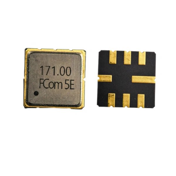
FSF-5050 series · 8-pad SMD
171 MHz RF SAW Bandpass Filter
FSF-5050-171M
Bandpass filtering across 167–175 MHz for VHF receiver front ends and telemetry receiver modules, in a compact 5.0 × 5.0 mm package.
Key Features
Key features
Specified passband
167–175 MHz
171 MHz ±4 MHz. This is an 8 MHz span over which insertion loss and amplitude ripple are specified; it is not a stated 3 dB bandwidth.
Insertion loss
6.5 dB max.
Across the specified passband 167–175 MHz with the specified matching for a 50 Ω source and load.
Amplitude ripple
2.1 dB p-p max.
Across fC ±4 MHz with the specified matching.
Operating temperature
−10 to +50 °C
Specified operating range.
Note: Electrical limits apply with the specified matching for a 50 Ω source and load. The 8 MHz passband span is not a stated 3 dB bandwidth.
Electrical Specifications
Electrical specifications
Values below apply to FSF-5050-171M. Device impedances and external source / load impedances are listed separately to support matching-network evaluation.
Scroll horizontally to view all columns.
| Parameter | Min. | Typ. | Max. | Unit | Condition / definition |
|---|---|---|---|---|---|
| Center frequency | — | 171.0 | — | MHz | Value shown in the Typ. column of the FCom datasheet |
| Specified passband | 167–175 (specified range) | MHz | fC ±4 MHz; not a stated 3 dB bandwidth | ||
| Insertion loss | — | — | 6.5 | dB | Across 167–175 MHz; specified matching |
| Amplitude ripple | — | — | 2.1 | dB p-p | Across fC ±4 MHz; specified matching |
| Attenuation · lower stopband | 50 | — | — | dB | 71–132.2 MHz; referenced to 0 dB |
| Attenuation · upper stopband | 42 | — | — | dB | 209.8–271 MHz; referenced to 0 dB |
| Operating temperature | −10 | — | +50 | °C | Operating range |
| Input impedance at fC | 390 Ω ∥ 300 pF | R ∥ C | Device equivalent impedance; not a 50 Ω port | ||
| Output impedance at fC | 1164 Ω ∥ 374 pF | R ∥ C | Device equivalent impedance; not a 50 Ω port | ||
| Source / load impedance | 50 / 50 | Ω | Measurement environment with specified matching | ||
“—” means no value is stated. R ∥ C denotes a resistance in parallel with a capacitance. The FCom datasheet does not state a separate measurement temperature; the operating range must not be treated as a stated test temperature.
Typical Applications
Typical applications
01 / VHF RECEIVERS
Receiver front-end filtering
Select the 167–175 MHz receive band and attenuate signals in the specified lower and upper stopbands. Include the filter insertion loss in the receiver gain and sensitivity budget.
02 / TELEMETRY & MONITORING
Receiver-module signal conditioning
Provide band selection for telemetry and remote-monitoring receivers operating within the specified passband. Check the required signal bandwidth and operating temperature against the module requirements.
Integration Notes
Integration notes
Evaluate with the specified matching
The datasheet lists these component values for the matched 50 Ω source / load environment. Confirm network orientation and component placement against the intended signal path before board evaluation.
- C1
- 10 pF
- L1
- 37 nH
- C2
- 8 pF
- L2
- 40 nH
Check the complete RF path
- Use the actual source and load requirements when reviewing the matching network.
- Keep RF interconnects short and provide a low-inductance ground path for ground and case-ground pads.
- Confirm pin orientation and signal direction; the input and output equivalent impedances are different.
- Evaluate the assembled board across its required signal band and operating temperatures.
Package & Pin Assignment
Package & pin assignment
5.0 × 5.0 mm
8-pad SMD package · 1.5 mm max height
Use the dimensioned drawing in the FCom datasheet when reviewing the mechanical fit and PCB layout. Confirm the drawing orientation before assigning pads.
Pins 2 and 6 retain the Input/Output labels used in the FCom pin table. Contact FCom if a different pin configuration is required.
| Pin number | Function |
|---|---|
| 2 | Input / Output |
| 6 | Input / Output |
| 1, 3, 5, 7 | Ground |
| 4, 8 | Case Ground |
Selection and Design-In Support
Selection and design-in support
Share your application requirements with FCom to review whether FSF-5050-171M fits the intended receiver design.
Signal requirements
Center frequency, occupied signal bandwidth, passband limits and required attenuation.
Interface and environment
Source / load requirements, matching approach, PCB constraints and temperature range.
Evaluation and ordering
Sample quantity, estimated annual usage and confirmation of the complete ordering code.
Engineering Questions
Frequently asked questions
Is the 8 MHz passband a 3 dB bandwidth?
No. The specified passband is 167 to 175 MHz, or 171 MHz ±4 MHz. This is an 8 MHz span over which insertion loss and amplitude ripple are specified. A 3 dB bandwidth is not stated in the FCom datasheet.
Can this filter connect directly to a 50 Ω source and load?
The published limits apply with the specified matching. At the center frequency, the filter input is 390 Ω in parallel with 300 pF and the output is 1164 Ω in parallel with 374 pF. These device impedances are different from the 50 Ω source and load used for the matched measurement.
How are the stopband attenuation limits referenced?
The attenuation limits are referenced to 0 dB, as stated in the datasheet. They should not be treated as additional rejection relative to the passband insertion loss.
Can pins 2 and 6 be interchanged without checking the matching?
The FCom pin table labels both pins as Input/Output, while the specified input and output impedances differ. Confirm the intended signal direction, matching orientation and board layout before evaluating a reversed connection.
Is FSF-5050-171M a guaranteed drop-in replacement for another filter?
A matching center frequency and package size do not establish interchangeability. Compare the passband definition, loss, attenuation, device impedances, matching network, pin assignment and mechanical drawing for the specific design.
What should I include in a selection inquiry?
Include FSF-5050-171M, the required center frequency and passband, source and load requirements, operating temperature, application, sample quantity and estimated annual usage. Confirm the complete ordering code with FCom before placing an order.