
FCom Fuji Crystal · FSF-5050 Series · SAW Bandpass Filter
162 / 163 / 169 / 169.4 MHz SAW Bandpass Filters
FSF-5050-162M · FSF-5050-163M · FSF-5050-169M · FSF-5050-169M4
Four frequency options for VHF, IF and metering receivers in a compact 5.0 × 5.0 mm package. Select the response and operating range that fit your signal chain.
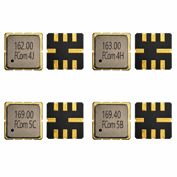
Find the right response
Choose by frequency and bandwidth definition
Compare the bandwidth definition and temperature limits before selecting a model.
SAW Filter · 162 MHz
FSF-5050-162M
162 MHz
3 dB bandwidth: 8.0 MHz typ. · minimum 6 MHz
- Insertion loss · typ. / max.
- 1.6 / 2.8 dB at center frequency
- Amplitude ripple
- 2.2 dB typ. / 4.7 dB p-p max. over 159–165 MHz
- Operating temperature
- −40 to +85 °C
SAW Filter · 163 MHz
FSF-5050-163M
163 MHz
Specified passband: 159–167 MHz (fC ±4.0 MHz). Not a 3 dB bandwidth.
- Insertion loss · typ. / max.
- 6.0 / 6.5 dB over 159–167 MHz
- Amplitude ripple
- 1.3 dB typ. / 2.1 dB p-p max.
- Operating temperature
- −10 to +50 °C
SAW Filter · 169 MHz
FSF-5050-169M
169 MHz
3 dB bandwidth: 8.8 MHz typ. · minimum 6.0 MHz
- Minimum insertion loss (ILmin)
- 1.5 dB typ. / 2.8 dB max.
- Stopband attenuation
- 42 dB min. / 54 dB typ. over 119–139 MHz, relative to ILmin
- Operating temperature
- −10 to +70 °C
SAW Filter · 169.4 MHz
FSF-5050-169M4
169.4 MHz
3 dB bandwidth: 500 kHz typ. Narrowband metering receiver filtering.
- Insertion loss · typ. / max.
- 2.0 / 3.0 dB including matching-element loss
- Passband loss
- 0.4 dB typ. / 3.0 dB max. over 169.3–169.5 MHz, relative to ILmin
- Operating temperature
- −40 to +85 °C
Read the definitions: 163M specifies a passband interval. The other three models list 3 dB bandwidth. The shared package does not establish electrical interchangeability.
Electrical Specifications
Electrical specifications
All four models specify a 50 Ω source and a 50 Ω load under their applicable test and matching conditions. “—” means no value is specified; typical values are not guaranteed limits.
Scroll horizontally to view all columns.
FSF-5050-162M
| Parameter | Min. | Typ. | Max. | Unit | Condition / definition |
|---|---|---|---|---|---|
| Center frequency | — | 162.00 | — | MHz | At 25 °C |
| Insertion loss | — | 1.6 | 2.8 | dB | At the center frequency |
| 3 dB bandwidth | 6 | 8 | — | MHz | 3 dB bandwidth definition |
| Amplitude ripple | — | 2.2 | 4.7 | dB p-p | 159–165 MHz (fC ±3.0 MHz) |
| Operating temperature | −40 | — | +85 | °C | Operating range |
Single-ended measurement with 50 Ω source and load under the applicable test and matching conditions.
FSF-5050-163M
| Parameter | Min. | Typ. | Max. | Unit | Condition / definition |
|---|---|---|---|---|---|
| Center frequency | — | 163.0 | — | MHz | Center frequency |
| Insertion loss | — | 6.0 | 6.5 | dB | 159–167 MHz (fC ±4.0 MHz) |
| Specified passband | 159–167 (specified range) | MHz | Passband limits; not a 3 dB bandwidth | ||
| Amplitude ripple | — | 1.3 | 2.1 | dB p-p | 159–167 MHz (fC ±4.0 MHz) |
| Operating temperature | −10 | — | +50 | °C | Operating range |
50 Ω source and load under the specified matching conditions. External matching is required; the 50 Ω test environment does not imply a directly matched device.
FSF-5050-169M
| Parameter | Min. | Typ. | Max. | Unit | Condition / definition |
|---|---|---|---|---|---|
| Center frequency | — | 169.00 | — | MHz | Center frequency |
| Minimum insertion loss (ILmin) | — | 1.5 | 2.8 | dB | ILmin reference level |
| 3 dB bandwidth | 6.0 | 8.8 | — | MHz | 3 dB bandwidth definition |
| Stopband attenuation | 42 | 54 | — | dB | 119–139 MHz; relative to ILmin |
| Operating temperature | −10 | — | +70 | °C | Operating range |
50 Ω source and load. The stated attenuation applies only to 119–139 MHz; it is not a rejection value for the entire stopband.
FSF-5050-169M4
| Parameter | Min. | Typ. | Max. | Unit | Condition / definition |
|---|---|---|---|---|---|
| Center frequency | — | 169.40 | — | MHz | Center frequency |
| Insertion loss | — | 2.0 | 3.0 | dB | Includes matching-element loss |
| 3 dB bandwidth | — | 500 | — | kHz | Typical 3 dB bandwidth |
| Passband loss | — | 0.4 | 3.0 | dB | 169.3–169.5 MHz; relative to ILmin |
| Operating temperature | −40 | — | +85 | °C | Operating range |
50 Ω source and load with matching required. The 169.3–169.5 MHz passband-loss interval is separate from the typical 500 kHz 3 dB bandwidth.
Typical Applications
Typical applications
Match the filtering stage to the receiver frequency plan and required signal bandwidth.
FSF-5050-162M
VHF receiver filtering
Front-end or intermediate-frequency filtering in 162 MHz receiver stages, monitoring equipment and RF modules.
FSF-5050-163M / 169M
Telemetry and remote monitoring
Signal conditioning in industrial wireless and data-acquisition receivers using the selected 163 MHz or 169 MHz filtering stage.
FSF-5050-169M4
169.4 MHz metering receivers
Narrowband RF filtering for wireless gas, water and heat meter receiver front ends, and telemetry around 169.4 MHz.
Before PCB design-in
Integration notes
Confirm the interface and matching network for the selected model, then evaluate the response in your receiver circuit.
- Matching: 163M and 169M4 explicitly require matching. Do not transfer a network between models solely because the package is the same.
- Insertion-loss reference: 162M is specified at center frequency; 163M across its stated passband; 169M as minimum insertion loss; 169M4 includes matching-element loss.
- Grounding and layout: connect the listed ground and case-ground pads, keep RF routes short, and verify the package orientation against the applicable drawing.
- Temperature: check each model’s operating range separately. The four models do not share a single temperature rating.
Package & Pin Assignment
Package & pin assignment
Shared package information for all four models in the supplied FCom specifications.
5.0 × 5.0 mm
8-pad SMD · 1.5 mm max. height
Use the applicable mechanical drawing for dimensions and orientation. Contact FCom to discuss other pin configurations.
| Pin number | Function |
|---|---|
| 2 | Input / Output |
| 6 | Input / Output |
| 1, 3, 5, 7 | Ground |
| 4, 8 | Case Ground |
Pin functions follow the FCom specifications. Confirm signal direction and connection orientation for the selected configuration before layout or substitution.
Selection and Design-In Support
Selection and design-in support
Share your frequency plan, passband, interface impedances and temperature range with FCom to discuss the model and matching requirements. Include sample quantity and estimated annual volume when confirming the ordering configuration.
Engineering Questions
Frequently asked questions
How do I choose between these four models?
Start with the required center frequency, then check the bandwidth definition and temperature range. FSF-5050-162M and FSF-5050-169M specify 3 dB bandwidths of 8.0 MHz and 8.8 MHz typical. FSF-5050-163M specifies a 159–167 MHz passband. FSF-5050-169M4 specifies a 500 kHz typical 3 dB bandwidth for narrower-band filtering around 169.4 MHz.
Is the 159–167 MHz passband of FSF-5050-163M a 3 dB bandwidth?
No. It is the specified interval over which insertion loss and amplitude ripple are given. It spans 8 MHz, but the supplied FCom specification does not identify that interval as a 3 dB bandwidth.
Why does FSF-5050-169M4 list both 500 kHz and 169.3–169.5 MHz?
500 kHz is the typical 3 dB bandwidth. The 169.3–169.5 MHz interval is where passband loss is specified relative to minimum insertion loss. These describe different aspects of the filter response and should not be used interchangeably.
Can these filters connect directly to any 50 Ω circuit?
All four models specify 50 Ω source and load conditions. FSF-5050-163M and FSF-5050-169M4 explicitly require matching. Confirm the device interface, matching network and PCB layout for the selected model before connection; a 50 Ω test environment alone does not establish a direct match.
Are the four models interchangeable on the same PCB?
A shared 5.0 × 5.0 mm package and the listed FCom pin assignments do not establish electrical interchangeability. Center frequency, bandwidth, insertion-loss conditions, operating temperature and matching requirements differ. Verify the exact model and connection orientation before substitution.
What information should I include in a technical inquiry?
Include the selected model or center frequency, required passband or bandwidth definition, source and load impedances, operating temperature, application, sample quantity and estimated annual volume. The complete ordering code should be confirmed for the selected configuration.