
FSF-5050 Series · Receiver RF / IF Filtering
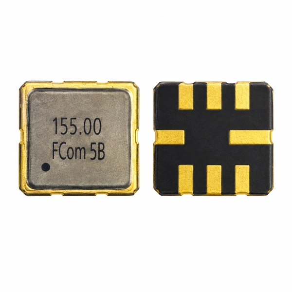
155 MHz SAW Bandpass Filter
FSF-5050-155M
A 155 MHz SAW filter with a specified passband from 151 to 159 MHz for receiver RF and IF stages. Defined insertion-loss and ripple limits support selection for paging, telemetry and security receiver designs.
Key selection points
Check passband, loss and temperature
Insertion loss and amplitude ripple apply within 151–159 MHz. Electrical characteristics depend on the matching circuit and test conditions.
Specified passband
151–159 MHz
fC ±4 MHz. Bandwidth listed as 8 MHz min.; no 1 dB or 3 dB definition stated.
Insertion loss
6.5 dB max.
Within fC ±4 MHz (151–159 MHz), with the specified matching network.
Amplitude ripple
2.1 dB p-p max.
Within fC ±4 MHz.
Operating temperature
−10 to +50 °C
For the listed FCom configuration.
Package
5.0 × 5.0 mm
8-pad SMD package · 1.5 mm max. height.
Interface
Contact FCom
Input and output impedances are not assigned in the available datasheet.
Read the bandwidth definition: the 8 MHz minimum and 151–159 MHz passband do not establish a 1 dB or 3 dB bandwidth. No such definition is stated in the supplied FCom datasheet.
Electrical Specifications
155 MHz filter specifications
Insertion loss and amplitude ripple apply within 151–159 MHz. Electrical characteristics depend on the matching circuit and test conditions.
Scroll horizontally to view all columns.
| Parameter | Min. | Typ. | Max. | Unit | Conditions / notes |
|---|---|---|---|---|---|
| Center frequency, fC | — | 155.00 | — | MHz | No Min./Max. classification stated |
| Bandwidth, BW | 8 | — | — | MHz | Specified passband: 151–159 MHz; no 1 dB or 3 dB definition stated |
| Insertion loss | — | — | 6.5 | dB | fC ±4 MHz (151–159 MHz) |
| Amplitude ripple | — | — | 2.1 | dB p-p | fC ±4 MHz (151–159 MHz) |
| Operating temperature | −10 | — | +50 | °C | For the listed FCom configuration |
| Input impedance | — | — | — | Ω | Not specified; contact FCom |
| Output impedance | — | — | — | Ω | Not specified; contact FCom |
“—” means no value or condition is stated for that entry. The center frequency has no Min./Typ./Max. classification. The source does not specify a general measurement temperature. The 8 MHz minimum bandwidth and 151–159 MHz passband do not establish a 1 dB or 3 dB bandwidth.
Typical applications
155 MHz filtering in receiver designs
Paging receivers
Provides bandpass filtering around 155 MHz in paging receiver front ends. Check that the required signal band fits the specified passband.
Telemetry & data acquisition
Filters 155 MHz RF or IF stages in telemetry, remote-control and wireless data-acquisition receivers before downstream signal processing.
Security & alarm receivers
Provides 155 MHz bandpass filtering in receiver modules. Evaluate the required rejection and gain budget for the complete signal path.
Integration notes
Confirm port impedance and matching
The FCom specification does not assign numerical input or output impedances. Confirm the selected configuration’s interface and matching conditions before schematic or PCB release.
Interface
Provide source and load impedance and whether the circuit is single-ended or differential. The available FCom datasheet asks customers to contact FCom for input and output impedance.
Response and evaluation
- Define passband, insertion-loss budget, ripple and the rejection needed outside the signal band.
- Verify performance with the intended matching network, PCB layout and measurement reference planes.
- Confirm the package orientation and pad numbering before release.
8-pad SMD package
Package & pin assignment
5.0 × 5.0 mm
8-pad SMD · 1.5 mm max. height
The pin functions below apply to the listed FCom configuration. Verify viewing direction and pad numbering before PCB layout.
For other pin configurations, please contact FCom.
| Pin | Function |
|---|---|
| 2 | Input / Output |
| 6 | Input / Output |
| 1, 3, 5, 7 | Ground |
| 4, 8 | Case Ground |
Selection and design-in support
Define the requirements for your receiver
Share your required passband, source/load requirements and operating temperature with FCom to discuss the suitable configuration. Include the application, sample quantity and expected volume.
Engineering questions
Frequently asked questions
What does the 8 MHz bandwidth specification mean?
The FCom datasheet lists 8 MHz in the minimum bandwidth column and specifies a passband from 151 to 159 MHz, or fC ±4 MHz. Insertion loss and ripple are specified within that interval. No 1 dB or 3 dB bandwidth definition is stated.
Can FSF-5050-155M be used in both RF and IF receiver stages?
The FCom datasheet lists 155 MHz filtering in receiver RF and IF signal chains, including paging, telemetry, remote-control, data-acquisition and security receivers. Use it where the 151–159 MHz specified passband and electrical limits meet the receiver requirements.
Can the filter connect directly to a 50 Ω circuit?
The available FCom datasheet asks customers to contact FCom for input and output impedance. A direct 50 Ω connection is therefore not established by the published data. Confirm the port impedances, interface type and matching conditions before circuit evaluation.
Is the operating range −40 to +85 °C?
No. The operating temperature range listed for FSF-5050-155M is −10 to +50 °C. Do not apply another model’s temperature range or treat a reference device’s storage range as this product’s operating range.
Which pins carry the signal?
The listed FCom configuration uses pins 2 and 6 as Input/Output, pins 1, 3, 5 and 7 as Ground, and pins 4 and 8 as Case Ground. Confirm pad numbering and viewing direction before PCB release. Contact FCom for other pin configurations.
What information should I provide for selection?
Provide the model or center frequency, required passband and bandwidth criterion, source and load requirements, operating temperature, application, sample quantity and estimated annual volume. The complete ordering code should be confirmed with FCom for the selected configuration.