
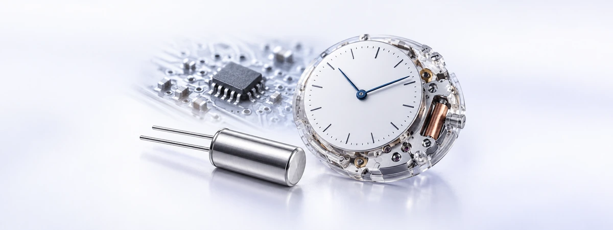
Quartz Timing · Technical Guide
The familiar 32.768 kHz watch crystal provides a convenient time base for quartz watches and real-time clocks. Its frequency is easy to divide into seconds, while a suitable oscillator circuit supports continuous timekeeping with low power consumption.
FCom Fuji Crystal · Technical Guide
From crystal oscillations to seconds
A quartz crystal is a passive resonator. The oscillator amplifier, usually inside the RTC or microcontroller, supplies energy to sustain vibration. The resulting clock feeds counters that track seconds, minutes, hours and dates. A crystal alone does not produce a powered digital clock output. [1]
Binary division:
32,768 Hz ÷ 215 = 1 Hz
1 nominal output cycle = 1 second
Low-power timekeeping can continue while the main processor sleeps. RTCs with a supported backup supply can also retain time when system power is removed. This makes the architecture useful for watches, data logging and scheduled wake-ups. The backup function belongs to the RTC circuit, not the crystal. [1]
Tuning-fork crystals and AT-cut crystals
Many 32.768 kHz watch crystals use a tuning-fork structure with two vibrating prongs. This flexural vibration mode differs from the thickness-shear mode of an AT-cut crystal. The internal resonator structure cannot be identified reliably from the external package shape alone. [2]
| Characteristic | Tuning-fork crystal | AT-cut crystal |
|---|---|---|
| Typical vibration mode | Flexural vibration of the prongs. | Thickness-shear vibration of a quartz plate. |
| Common frequency region | Low-frequency kHz operation, including 32.768 kHz. | Commonly used for MHz timing references. |
| Typical system role | Watch timekeeping and RTC clock source. | Processor, communications and other system clocks. |
They are not interchangeable simply because both contain quartz. Match the resonator frequency and electrical parameters to the oscillator circuit.
Understanding timekeeping error
Frequency error is often expressed in parts per million, or ppm. For a constant error, accumulated time error follows directly from elapsed time:
Time error (seconds) = frequency error (ppm) × elapsed time (seconds) ÷ 1,000,000
| Error magnitude | After 24 hours | After 30 days |
|---|---|---|
| 5 ppm | 0.432 seconds | 12.96 seconds |
| 10 ppm | 0.864 seconds | 25.92 seconds |
| 20 ppm | 1.728 seconds | 51.84 seconds |
Calculated examples, not FCom product measurements. Positive frequency error makes the clock gain time; negative error makes it lose time. Actual error changes with operating conditions.
Room-temperature tolerance is only one part of the budget
Conventional tuning-fork crystals have an approximately parabolic frequency-temperature response around a turnover temperature, often near room temperature. Frequency falls relative to its turnover value on either side. The actual turnover temperature and curvature are device-specific. [3]
Initial tolerance, load mismatch, temperature and aging contribute to the final error. A room-temperature adjustment does not remove temperature drift. Where required, use supported RTC calibration or temperature compensation and validate accuracy across the intended temperature range. [3]
Choosing a crystal for an RTC
Match the specified load capacitance
A parallel-resonant crystal is specified at a particular load capacitance, CL. In a conventional Pierce oscillator, insufficient effective loading tends to raise frequency; excessive loading tends to lower it. Some RTCs integrate load capacitors, so external capacitors are not automatically required. [4]
CL ≈ (CA × CB) ÷ (CA + CB) + Cstray
CA and CB represent the effective capacitance from each oscillator node to ground, including applicable internal and pin capacitance. Cstray represents the remaining effective parasitic contribution. Avoid counting the same capacitance twice. [5]
For an illustrative CL of 12.5 pF and Cstray of 2 pF, equal effective branches would each be 21 pF: 21 ÷ 2 + 2 = 12.5 pF. This does not automatically mean fitting two external 21 pF capacitors; subtract contributions already present and follow the IC guidance.
Check ESR, drive level and startup
Equivalent series resistance, or ESR, represents resonator losses. The oscillator must provide adequate startup margin with the selected crystal’s maximum ESR and load. A smaller package can have different electrical requirements, even at the same nominal frequency. [6]
Keep crystal drive power within its specified limit. Do not assume the highest oscillator drive setting is best. Verify startup across supply voltage and temperature, and allow the stabilization time required by the IC before relying on its clock. [5]
For selection, specify frequency tolerance and its test temperature, CL, maximum ESR, drive limit, operating temperature, package and aging requirements. Review the complete crystal-and-IC combination before approving a replacement.
PCB layout and verification
- Place the crystal close to its oscillator pins and keep connections short.
- Keep switching nodes and fast digital signals away from the crystal circuit.
- Follow the IC manufacturer’s grounding and guard-ring recommendations.
- Control contamination and moisture that can introduce leakage or parasitic loading.
Test on the intended PCB, including startup and timekeeping in relevant power modes. Low-power crystal nodes are sensitive to probe capacitance; measuring them directly can disturb or stop oscillation. Prefer a supported buffered clock output or RTC time comparison for accuracy checks. [4] [6]
Frequently asked questions
Are 32.768 kHz and 32,768 Hz the same?
Yes. One kilohertz equals 1,000 hertz, so both expressions identify the same nominal frequency.
Why not use 32,000 Hz?
32,000 is not a power of two. It can be divided to 1 Hz with suitable counting logic, but fifteen divide-by-two stages produce 1 Hz directly from 32,768 Hz.
Does a 32.768 kHz crystal guarantee an accurate RTC?
No. It defines the nominal frequency. Actual accuracy depends on the crystal, capacitive loading, temperature, aging and circuit implementation.
Can I replace a crystal with a 32.768 kHz oscillator module?
Only if the receiving IC supports an external clock with compatible input levels. A powered oscillator output is not a drop-in replacement for a passive crystal across two oscillator pins. Check the required input mode and connections.
Discuss your RTC crystal requirements
For an FCom crystal inquiry, send your RTC or microcontroller part number, target load capacitance, maximum ESR, package, operating temperature and timekeeping accuracy requirements to FCom@fujicrystal.com. Include the oscillator schematic and any startup or drift measurements.
Technical references
- Microchip Technology: Real-Time Clock (RTCC) FAQs .
- NDK: Orientation Angles and Vibration Modes .
- Analog Devices: Timekeeping Accuracy, Automatic and Affordable .
- Analog Devices: Crystal Considerations with Analog Devices Real-Time Clocks (RTCs) .
- STMicroelectronics: AN2867 — Guidelines for Oscillator Design (PDF) .
- Microchip Technology: AN2648 — Selecting and Testing 32.768 kHz Crystal Oscillators for AVR Microcontrollers (PDF) .
Use the selected crystal and IC datasheets for device-specific limits. Reference examples do not establish compatibility for every oscillator circuit.


