
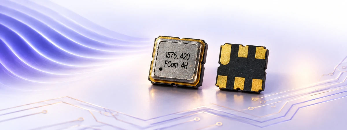
Surface acoustic wave (SAW) devices use mechanical waves concentrated near the surface of a solid to process electrical signals or measure physical changes. Their piezoelectric structures connect electrical circuits with acoustic behavior, enabling compact filters, resonators and sensing elements.
The key distinction: a SAW filter selects a frequency band; a SAW resonator provides a frequency-selective resonance; a SAW sensor measures changes in an acoustic response. These functions share a physical foundation, but their circuit requirements and specifications differ.
How SAW devices work
An interdigital transducer (IDT) consists of interleaved metal electrodes on a piezoelectric substrate. An alternating voltage produces mechanical deformation through the inverse piezoelectric effect, launching an acoustic wave. A receiving transducer converts that motion back into an electrical signal. This reversible coupling underpins many SAW structures. [1]
A useful first approximation relates the operating frequency to acoustic velocity and wavelength:
f ≈ vSAW / λ
Here, vSAW is the acoustic phase velocity and λ is the acoustic wavelength selected by the electrode pattern. For an illustrative velocity of 3,150 m/s and wavelength of 10.5 μm, the calculated frequency is 300 MHz. This example is not a product specification; actual behavior depends on the substrate, crystal orientation, electrodes and device structure.
A simple traveling-wave device can use separate transmitting and receiving IDTs. Other designs use resonators and acoustic reflectors, so the familiar two-transducer illustration does not describe every SAW filter.
Development of SAW technology
A milestone in practical SAW electronics was the 1965 work of Richard M. White and F. W. Voltmer on direct piezoelectric coupling to surface elastic waves. Their periodic electrode structure demonstrated an effective route between electrical signals and surface waves. [1]
Subsequent development combined electrode patterning, substrate selection and packaging to make compact frequency-selective components. Modern implementations include temperature-compensated SAW and layered substrate structures. These approaches address temperature drift and acoustic confinement, although their benefits depend on the particular design. Murata describes this progression in its overview of SAW filter technology. [2]
Sensing extends the same operating principle: instead of minimizing every environmental influence, a sensor measures a controlled change in the acoustic response and relates it to a physical quantity.
Filters, resonators and delay lines
| Device | Primary function | What to evaluate |
|---|---|---|
| SAW filter | Pass a specified frequency band and attenuate unwanted signals. | Passband, insertion loss, rejection and impedance. |
| SAW resonator | Provide a sharp acoustic resonance for a circuit or sensor. | Resonant frequency, equivalent circuit, loss and temperature behavior. |
| SAW delay line | Introduce an acoustic transit time between transducers. | Delay, phase response, loss and environmental sensitivity. |
| SAW sensing element | Convert a physical or chemical change into a measurable acoustic response. | Sensitivity, calibration, cross-sensitivity and readout method. |
A resonator alone does not generate a sustained clock signal. An oscillator also needs an active circuit and suitable feedback. Likewise, a frequency-selective component becomes a useful sensor only when its response, mounting and measurement system support the intended measurement.
SAW devices in RF systems
RF filters help separate wanted signals from nearby interference. Their response is shaped by acoustic structures, electrode geometry and circuit topology. Low passband loss preserves signal power, while adequate rejection reduces unwanted energy outside the operating band. Both must be evaluated over the required temperature and frequency ranges. [2]
SAW and bulk acoustic wave (BAW) filters use different acoustic structures. SAW devices guide energy near the surface; common BAW resonators use vibration through the thickness of a piezoelectric layer. Selection should follow the actual component specifications and system requirements. A single frequency threshold does not describe the capabilities of every conventional, compensated or layered SAW design. [3]
Temperature, strain and chemical sensing
Temperature sensing
Temperature can change acoustic velocity and device dimensions, shifting resonance frequency or propagation delay. A calibrated SAW sensing system uses this response to estimate temperature. Research has demonstrated passive wireless arrangements combining a SAW resonator, antenna and external reader. The reader supplies the interrogation energy and detects the returned response. [4]
Battery-free operation does not guarantee unlimited range. Antenna coupling, surrounding materials, reader sensitivity and installation geometry remain part of the system design.
Strain sensing and structural monitoring
Mechanical strain changes electrode spacing and acoustic propagation, allowing a SAW response to indicate deformation. Temperature can produce a simultaneous frequency shift, so separating the two effects is essential. Published work on lithium-niobate devices uses distinct sensing responses to determine temperature and strain together. [5]
Practical implementation also requires a mounting method that transfers strain consistently from the structure to the sensing element.
Chemical and vapor sensing
A sensitive coating can interact with a target vapor and change the acoustic response. Researchers have demonstrated SAW sensors with polymer layers containing nanoparticles for volatile organic compound detection. Performance depends on the coating and measurement conditions, including sensitivity, noise and response time. [6]
A chemical sensing result therefore describes a particular sensing structure and test environment; it does not establish chemical selectivity for an ordinary uncoated RF filter.
Device selection checklist
For an RF filter, translate the system requirements into measurable limits:
- Passband: specify frequency edges and the bandwidth definition, such as the 3 dB points.
- Loss and ripple: state the maximum permitted insertion loss and passband variation.
- Rejection: identify unwanted frequency ranges and required attenuation.
- Interfaces: confirm source and load impedances, matching conditions and PCB layout requirements.
- Operating conditions: check temperature range, input power, package and assembly requirements.
Qorvo’s filter guide explains the underlying RF terminology. [3] For a sensing application, add the measurement range, calibration method, environmental interference and reader arrangement. Compare datasheet limits under matching test conditions.
Frequently asked questions
Is a SAW device a quartz crystal oscillator?
No. Some SAW devices use quartz substrates, but SAW describes the acoustic operating mode. A complete oscillator includes active circuitry; a passive SAW resonator is only one possible frequency-selective element.
Can any SAW filter work as a temperature sensor?
A filter may exhibit temperature-dependent behavior, but useful sensing requires characterized sensitivity, repeatability and calibration. RF filters designed for temperature stability have a different objective.
Are all SAW sensors wireless?
No. SAW elements can use wired readout. Wireless operation requires a compatible interrogation method and antenna arrangement; it is a property of the complete sensing system.
Discuss your SAW component requirements with FCom. Send your target frequency, bandwidth, insertion-loss limit, rejection requirements, impedance, operating temperature and package constraints to FCom@fujicrystal.com. For sensing projects, include the measurement objective and readout method so suitability can be evaluated.
References
- White, R. M., and Voltmer, F. W. Direct Piezoelectric Coupling to Surface Elastic Waves. University of California, Berkeley, 1965. PDF.
- Murata. SAW filter technology overview.
- Qorvo. RF Filter Technology for Dummies, Qorvo 2nd Special Edition. Download page.
- Design and Characterization of Surface Acoustic Wave-Based Wireless and Passive Temperature Sensing System. Full research article.
- Novel Surface Acoustic Wave Temperature–Strain Sensor Based on LiNbO3 for Structural Health Monitoring. Full research article.
- Characteristics of Surface Acoustic Wave Sensors with Nanoparticles Embedded in Polymer Sensitive Layers for VOC Detection. Full research article.


