
Quartz Fundamentals · Technical Guide
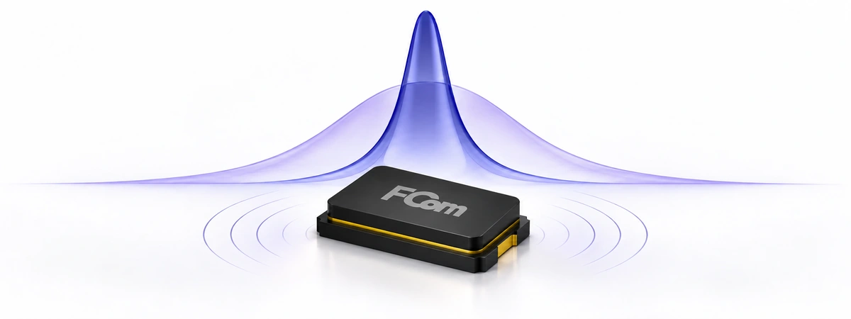
Resonant frequency identifies a characteristic response of an energy-storing system. For quartz timing designs, it helps explain why a crystal selects a narrow frequency region, how loading shifts the operating point, and why the complete oscillator must be evaluated alongside the resonator.
FCom Fuji Crystal · Technical Guide
1. What resonant frequency means
Resonance occurs when an excitation interacts strongly with a system’s energy exchange mechanism. In an LC circuit, energy moves between the capacitor’s electric field and the inductor’s magnetic field. In quartz, electrical excitation couples to mechanical vibration through the piezoelectric effect.
The observed response depends on the circuit and measurement point. A voltage-driven series RLC circuit has maximum current at resonance because inductive and capacitive reactances cancel. An ideal parallel LC network instead presents a high impedance at resonance. Therefore, resonance does not always mean maximum current everywhere. [1] [2]
Also distinguish an undamped natural frequency from a damped free-oscillation frequency or a driven response peak. These can differ when losses are significant or a different output quantity is measured.
2. Calculate LC resonant frequency
Angular frequency: ω₀ = 1 / √(LC)
Frequency: f₀ = 1 / (2π√(LC))
Period: T = 1 / f₀
Use inductance L in henries and capacitance C in farads. The result is f₀ in hertz; ω₀ is in radians per second. Convert component prefixes before calculating: 1 μH = 10−6 H and 1 pF = 10−12 F. [1]
Illustrative example: With L = 10 μH and C = 100 pF, f₀ ≈ 5.033 MHz and T ≈ 198.7 ns. Doubling C while keeping L fixed reduces the ideal frequency by √2, to approximately 3.559 MHz.
This is an ideal circuit calculation, not an FCom product measurement. Real components add resistance and parasitic reactance, so the assembled circuit can differ from the nominal calculation.
3. Understand Q factor and bandwidth
Quality factor is dimensionless. Its energy definition compares energy stored with energy dissipated during each cycle at resonance:
Q = 2π × (stored energy) / (energy lost per cycle)
For a series RLC circuit: Q = ω₀L / R = 1 / (ω₀CR)
For its half-power bandwidth: Q = f₀ / (f₂ − f₁)
The half-power points are approximately 3 dB below the response peak. For amplitude measured across the same resistance, this corresponds to 1/√2, or about 70.7% of peak amplitude—not 50%. Higher Q produces a narrower resonance for the same center frequency. [2]
Illustrative example: An isolated resonant response centered at 10 MHz with a 200 Hz half-power bandwidth has Q ≈ 50,000. That result describes resonance width; it does not establish a ±20 ppm frequency tolerance.
Unloaded Q describes the resonator’s internal losses. Loaded Q includes energy loss through the connected circuit and measurement coupling. A measured bandwidth generally reflects those loading conditions. Apply the simple bandwidth relation to an appropriate isolated resonance, not indiscriminately to a multiresonance filter or an oscillator’s output spectrum.
4. Apply the quartz crystal model
Near one vibration mode, represent a crystal by motional inductance Lm, capacitance Cm and resistance Rm in series, with shunt capacitance C0 across that branch. The motional elements represent mechanical behavior; C0 represents electrode and package capacitance. These are equivalent-circuit parameters, not discrete components inside the package. [3]
| Quantity | Formula | Interpretation |
|---|---|---|
| Series resonance, fs | 1 / (2π√(LmCm)) | The motional reactances cancel; crystal impedance is low near this frequency. |
| Unloaded antiresonance, fa | fs × √(1 + Cm/C0) | The motional branch interacts with C0, producing high terminal impedance. |
| Loaded resonance, fL | fs × √[1 + Cm/(C0 + CL)] | External load capacitance CL shifts the resonance between fs and fa. |
Losses make the exact impedance extrema and phase crossings differ from these ideal values. For a positive capacitive load in this model, fs < fL < fa. Increasing CL moves fL downward toward fs. The crystal’s nominal frequency may be specified at a particular CL, so it should not automatically be treated as fs. [4] [6]
Motional Q: Qm = 2πfsLm / Rm = 1 / (2πfsCmRm)
Use motional resistance Rm in this expression. Check how a datasheet defines ESR and its measurement conditions before substituting it. A resistance specified at a loaded operating point is not automatically identical to Rm. [4]
5. Find the actual oscillation frequency
A passive crystal cannot sustain oscillation without energy supplied by an active circuit. The amplifier, resonator and surrounding network establish the operating point. Startup requires adequate gain or negative-resistance margin; steady oscillation also depends on phase and amplitude limiting. A resonance formula alone cannot confirm reliable startup. [5]
- Identify the intended mode. Check fundamental or overtone operation and the specified series or load-resonant condition.
- Estimate the operating point. Use crystal model data, actual load capacitance and the oscillator IC’s recommended circuit.
- Measure a suitable output. Prefer a buffered clock output or the manufacturer’s approved test method to limit probe disturbance.
- Convert period to frequency. If N cycles occupy Δt seconds, f = N/Δt. For example, 1,000 cycles in 100 μs correspond to 10 MHz.
- Record conditions. Include temperature, supply, load, instrument reference accuracy and measurement uncertainty.
For a passive resonator, use a calibrated impedance or network-analyzer fixture and a suitable equivalent-circuit fit. Raw transmission bandwidth can include fixture and source/load losses; remove or model those effects before reporting intrinsic Q.
6. Select and validate a timing device
Start with the required frequency and oscillator interface. Then confirm resonance mode, specified CL, ESR limit, drive level, initial tolerance, temperature stability, aging and package. Fundamental and overtone devices require compatible oscillator circuits; overtone frequencies are not necessarily exact integer multiples of the fundamental. [6]
High Q supports sharp frequency discrimination, but does not guarantee low system jitter, fast startup or a particular ppm accuracy. Validate those requirements separately. Check startup margin and drive level over the intended supply and temperature range, following the oscillator IC documentation. [3] [5]
7. Frequently asked questions
Are resonant frequency and oscillation frequency identical?
Not necessarily. Resonance characterizes the passive network, while sustained oscillation depends on the complete active loop and its loading.
Does a higher Q guarantee better frequency accuracy?
No. Q describes losses and resonance sharpness. Calibration, temperature, aging and circuit loading still determine frequency error.
Can I calculate a crystal’s frequency from its load capacitors alone?
No. The crystal’s motional parameters establish the resonance. External capacitors adjust its loaded operating point.
Why does the measured Q change with the test fixture?
The fixture adds loading and losses. Distinguish the measured loaded Q from the resonator’s intrinsic Q and document the extraction method.
Can I substitute a series-specified crystal for a load-specified crystal?
Only after checking calibration conditions and oscillator compatibility. The same nominal frequency does not establish an interchangeable operating point.
Discuss your frequency requirements
For FCom selection support, provide the target frequency, oscillator IC, required mode, load capacitance, operating range and frequency budget. Contact FCom@fujicrystal.com to discuss suitable crystal specifications and validation needs.
Technical references
- OpenStax: University Physics Volume 2 — Resonance in an AC Circuit.
- MIT OpenCourseWare: Frequency Response: Resonance, Bandwidth, Q Factor (PDF).
- Analog Devices: Design a Crystal Oscillator to Match Your Application.
- Analog Devices: AN-1260 — Crystal Design Considerations for Video Decoders, HDMI Receivers, and Transceivers.
- STMicroelectronics: AN2867 — Guidelines for Oscillator Design (PDF).
- Analog Devices: Specifying Quartz Crystals.


