
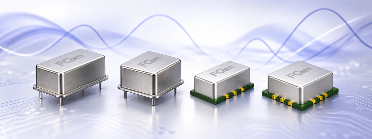
Frequency Control · OCXO Selection
Choosing an oven-controlled crystal oscillator requires more than comparing a stability number. The right OCXO must meet your temperature, phase-noise, start-up, power and interface requirements under the conditions your equipment will actually experience.
FCom Fuji Crystal · Technical Guide
How should you compare OCXOs? Start with the system error budget, then compare individual configurations at the same temperature range, carrier frequency, phase-noise offsets and warm-up endpoint. A temperature-stability limit, an aging rate and a warm-up error describe different behaviors and cannot replace one another.
What an OCXO controls
An OCXO uses a temperature-controlled oven to reduce the quartz resonator’s exposure to ambient temperature changes. This supports stable frequency generation, but the heater requires power and time to settle. Board temperature, airflow, supply quality and output loading remain relevant to the finished design.
Temperature stability describes frequency variation over a stated temperature range. Aging describes frequency change with elapsed time under specified conditions. Initial calibration error, supply sensitivity and load sensitivity are additional contributors. The total accuracy budget must account for the applicable terms without counting a term twice when it is already included in an overall specification. [4]
For unit comparison, 1 ppm equals 1,000 ppb. Thus, ±0.1 ppm equals ±100 ppb; neither value describes phase noise or automatically establishes a holdover duration.
FCom OCXO comparison: match the configuration
The following published model summaries provide a starting point for selection. Temperature limits belong to the stated range and configuration. Use the order-specific specification to establish guaranteed performance, available options and acceptance tests.
| Model | Package, L × W × H | Temperature stability | Selection consideration |
|---|---|---|---|
| FOC-1D | DIP, 20.3 × 12.7 × 11.0 mm | ±0.1 ppm, −30 to +70°C | Compact through-hole format; compare output and supply options. [1] |
| FOC-2D | DIP, 20.6 × 20.6 × 13.2 mm | ±0.1 ppm, −30 to +70°C | Alternative through-hole footprint; check pinout and height. [2] |
| FOC-3D | DIP, 25.4 × 25.4 × 12.7 mm | ±10 ppb, −30 to +70°C | SC-cut model for designs requiring a tighter temperature budget. |
| FOC-4D | DIP, 36.3 × 27.2 × 12.7 mm | ±5 ppb, −40 to +85°C | SC-cut option; allow for package area and heater demand. |
| FOC-5S | SMD, 14.7 × 9.6 × 8.2 mm | ±30 ppb, −40 to +85°C | Compact surface-mount format with HCMOS output. |
| FOC-5S-LN | SMD, 14.7 × 9.6 × 8.2 mm | ±10 ppb, −40 to +85°C | Low-noise option; specify the required carrier and noise mask. |
| FOC-6S | SMD, 25.4 × 22.1 × 11.0 mm | ±10 ppb, 0 to +70°C, referenced to +25°C | SC-cut SMD option; use the temperature range attached to the selected grade. [3] |
Source basis: FCom model selection summaries; the FOC-6S row follows its electrical-specification table. These examples are not a statement of stock, lead time or lifecycle status. Confirm the current orderable part number and datasheet revision with FCom before design release.
Compare phase noise and warm-up on equal terms
Keep carrier frequency and offset together
Phase noise is expressed in dBc/Hz at an offset from the carrier. A result at 10 kHz offset cannot substitute for a requirement at 10 Hz. Compare the same carrier frequency, output configuration and measurement conditions, and distinguish typical results from maximum limits.
| Model | Carrier | 10 Hz offset | 10 kHz offset | Basis |
|---|---|---|---|---|
| FOC-4D | 10 MHz | −120 dBc/Hz | −150 dBc/Hz | Maximum values in the published model specification summary. |
| FOC-5S | 20 MHz | −98 dBc/Hz | −152 dBc/Hz | Typical values in the published product summary. |
| FOC-6S | 20 MHz | −115 dBc/Hz | −150 dBc/Hz | Maximum-column values in the electrical-specification table. [3] |
These rows are not a direct performance ranking: carrier frequencies and typical/maximum definitions differ. For FOC-1D, FOC-2D, FOC-3D and FOC-5S-LN, request a noise mask tied to the intended configuration instead of extending another model’s figures to them.
RMS jitter also requires an integration bandwidth. Two phase-noise points alone do not define integrated jitter; use the relevant spectrum and integration limits for the receiving circuit. [5]
Define what “warmed up” means
A warm-up claim needs an elapsed time, ambient temperature, frequency-error band and reference definition. FOC-1D and FOC-2D summaries describe approximately two minutes to ±0.1 ppm at +25°C. That condition must not be transferred to another model. [1] [2]
The FOC-6S datasheet specifies ±10 ppm after two minutes at +25°C, referenced to the frequency after one hour. Its separate ±10 ppb temperature-stability entry does not mean that ±10 ppb is reached after two minutes. Qualify the time needed to meet your actual error budget, including cold-start conditions. [3]
Turn system requirements into a shortlist
- Telecom and holdover: define allowable time error, outage duration, temperature profile, aging and the residual frequency error when disciplining stops.
- RF synthesis and instrumentation: define the phase-noise mask at relevant offsets and the reference frequency accepted by the PLL or instrument.
- Space-constrained equipment: check SMD footprint, height, assembly limits and thermal behavior inside the enclosure.
- Power-limited equipment: budget heater start-up current separately from steady-state power, including the lowest operating temperature.
For a simplified holdover estimate with constant fractional frequency error:
Time error ≈ fractional frequency error × elapsed time
Example: 10 ppb × 3,600 seconds = 36 microseconds.
This calculated example assumes a constant 10 ppb error and zero initial time offset. It excludes changing temperature, aging and control-loop effects; it is not a measured holdover result for any FCom model.
During prototype testing, check supply droop during heater start-up, noise on the tuning input, output loading and thermal changes caused by fans or nearby processors. Validate frequency settling in the assembled enclosure. Use the specified output level and load; HCMOS and sine-wave interfaces are not interchangeable.
Before procurement approval, establish the exact part number, current lifecycle status, supported options, datasheet revision and qualification requirements. A family name alone does not establish availability or form-fit-function interchangeability.
Frequently asked questions
Does the smallest ppb value identify the best OCXO?
It identifies one aspect of performance under specified conditions. The application may instead be limited by close-in phase noise, aging, power, warm-up or output compatibility.
Can I apply a 10 MHz phase-noise specification to 20 MHz?
No. Use data for the intended carrier and output option. Comparing different carrier frequencies without accounting for the signal chain can lead to an incorrect selection.
Does a two-minute warm-up guarantee final accuracy?
Only the stated warm-up error band and test conditions apply. Temperature stability, initial accuracy and longer-term settling require their own specifications.
Does an OCXO alone guarantee PTP or SyncE performance?
No. It supplies a frequency reference within a larger timing system. System compliance also depends on synchronization control, distribution, environmental behavior and the applicable equipment tests.
Discuss your OCXO requirements with FCom
Send your frequency, supply voltage, output and load, temperature range, stability budget, phase-noise mask, warm-up target, package limits and quantity to FCom@fujicrystal.com. Include the holdover requirement where relevant so our team can review the configuration and supporting specifications.
Technical references
- FCom FOC-1D product information.
- FCom FOC-2D product information.
- FCom FOC-6S datasheet: electrical specifications and package information (PDF).
- NI: What Clock Error Means to Your Measurement System.
- Analog Devices MT-008: Converting Oscillator Phase Noise to Time Jitter (PDF).
Additional model data: FCom FOC-3D, FOC-4D, FOC-5S and FOC-5S-LN published product summaries. Order-specific specifications govern final selection.


