
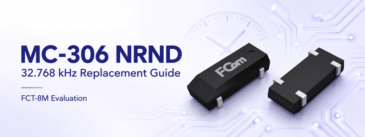
The Epson MC-306 is a 32.768 kHz quartz crystal used with an external oscillator circuit for timekeeping. For teams maintaining an existing RTC design, replacement selection now involves both lifecycle planning and circuit qualification. Matching frequency and package length alone is insufficient to approve a substitute.
Key decision: Epson’s August 2025 NRND notice includes MC-306 M/F. FCom FCT-8M is a candidate for evaluation, but an unchanged PCB, reliable startup and equivalent timekeeping must be verified for the exact parts and application.
MC-306 NRND status and published schedule
Epson’s official NRND notice No. 25-003E lists MC-306 M/F among the affected products. NRND means “not recommended for new designs.” The notice also provides the following planned lifecycle milestones.
| Milestone | Published plan |
|---|---|
| EOL start | June 2026 |
| Last-time buy | End of December 2026 |
| Last shipment | End of June 2027 |
| Recommended alternative in the notice | N/A |
These are the manufacturer’s published plans, not confirmation of current stock, order acceptance or shipment availability. Confirm the exact ordering code and latest schedule with Epson or your authorized supplier before making a last-time purchase.
A controlled migration should connect purchasing dates with engineering milestones: sample availability, circuit evaluation, production trials and final component approval.
Is FCT-8M a drop-in replacement?
The FCom FCT-8M product page lists a 32.768 kHz tuning-fork crystal in the same 8.0 × 3.8 mm package class. This makes it a candidate for review, rather than proof of interchangeability.
| Parameter | Epson MC-306 | FCom FCT-8M |
|---|---|---|
| Nominal frequency | 32.768 kHz | 32.768 kHz |
| Body dimensions | 8.0 × 3.8 × 2.54 mm maximum | 8.0 × 3.8 × 2.9 mm in FCom’s selection guide; confirm drawing |
| Operating temperature | −40 to +85°C | −40 to +90°C |
| Load capacitance | Order-dependent; 12.5 pF standard | 6 / 7 / 9 / 12.5 pF or specified |
| Maximum ESR | 50 kΩ | 50 kΩ |
| Maximum drive level | 1.0 µW | 1.0 µW |
| Frequency tolerance | ±20 / ±50 ppm standard options | ±5 / ±10 / ±20 ppm options |
| First-year aging | ±3 ppm maximum at +25°C | ±3 ppm typical |
Sources: Epson MC-306 product brief, the FCT-8M product page and FCom’s RTC crystal selection guide. Final approval must use the controlled specifications for the selected ordering codes. Typical aging is not a guaranteed maximum.
Check the height difference. The published FCT-8M guide dimension exceeds MC-306’s maximum height. Check enclosure and shield clearance, terminal geometry, pad overlap and placement orientation. Epson’s brief also instructs designers to leave pins 2 and 3 unconnected to external devices; verify the candidate’s connection drawing separately.
Review the RTC oscillator circuit
Match effective load capacitance
In a typical Pierce circuit, a useful first approximation is:
CL ≈ (C1 × C2) / (C1 + C2) + Cstray
Include the RTC’s internal capacitance and PCB parasitics. Equal external capacitors are not each equal to the crystal’s specified load. A change in crystal load specification can require capacitor or register changes and can shift the measured frequency.
Verify startup margin and crystal drive
Matching maximum ESR does not establish sufficient oscillator margin. Check the MCU or RTC manufacturer’s criteria across supply, temperature and component tolerances. Separately verify crystal drive: dissipation depends on crystal current and ESR, and must remain below the specified limit.
STMicroelectronics application note AN2867 explains these relationships for its supported devices. Use the guidance for your actual host IC when setting acceptance limits. Probe capacitance can disturb the oscillator, so choose an appropriate measurement method.
Measure timekeeping and backup current
Initial tolerance is only one part of the error budget. Include temperature drift, aging and load mismatch. Characterize accuracy through the product’s operating profile and verify any calibration settings after substitution. Measure backup current with the RTC running, including supply switchover and low-battery conditions.
Replacement validation checklist
- Capture the baseline. Record the complete MC-306 ordering code, original circuit, load components, oscillator settings and existing test limits.
- Approve mechanical fit. Compare controlled drawings, pad locations, terminal connections, body height and assembly requirements.
- Define the candidate. Agree on FCT-8M load capacitance, tolerance, temperature range and guaranteed limits before ordering qualification samples.
- Test operating corners. Measure startup time and reliability at minimum supply and temperature extremes, including cold starts and backup transitions.
- Evaluate the assembled board. Check frequency, current and noise sensitivity with nearby switching circuits active. Review short routing, leakage and board cleanliness.
- Release the change. Record results, required capacitor or firmware changes, approved part codes and production inspection criteria before updating the BOM.
Frequently asked questions
Is MC-306 a CMOS oscillator?
No. It is a passive crystal unit requiring an oscillator circuit in an RTC, MCU or other device. It does not provide a powered CMOS clock output by itself.
Does NRND mean existing MC-306 boards stop working?
No. NRND is a lifecycle designation. Existing hardware should continue to be assessed against its original operating requirements, while procurement and future production need a supply plan.
Can the existing capacitors remain unchanged?
Possibly, if the selected crystal and actual circuit produce the required effective load and pass validation. Retaining the same nominal frequency does not settle that question.
Request an FCT-8M replacement review
Send the existing MC-306 part number, MCU or RTC model, schematic, load capacitance, height limit, temperature range and expected volume to FCom@fujicrystal.com. Include your startup, backup-current and timekeeping requirements so the candidate can be defined for evaluation.
For related design guidance, see the 32.768 kHz RTC crystal selection guide.


