
RTC Crystal Design · Lifecycle Planning
Replacing an MC-146 32.768 kHz crystal requires more than matching frequency and package size. This guide covers the published NRND notice, electrical compatibility, PCB layout and the checks needed to qualify a long-narrow replacement.
FCom Fuji Crystal · Technical Guide
MC-146 NRND: what the official notice says
Epson’s August 2025 notice 25-003E lists MC-146 M/F among products not recommended for new designs. Its table uses shared schedule cells for the listed group and gives the following planned milestones. [1]
- EOL start after: June 2026.
- Last-time buy: end of December 2026.
- Last shipment: end of June 2027.
- Recommended alternative: N/A for MC-146 M/F.
These are the plans recorded in that notice, not a guarantee of current order acceptance or delivery. Confirm applicability to the complete ordering code and obtain the latest schedule from Epson or its authorized sales channel. NRND does not, by itself, mean that all shipments have already stopped.
For an existing design, coordinate component qualification with purchasing, firmware and manufacturing. Reserve time for samples, production-board testing and any capacitor or footprint changes before committing the replacement to the bill of materials.
Establish the MC-146 design baseline
MC-146 is a passive tuning-fork crystal, not a powered oscillator module. It works with the oscillator circuit in an MCU or RTC. Epson’s series brief provides the following reference values; use the specification for your exact ordering code when approving a substitute. [2]
| Parameter | Published value | Replacement check |
|---|---|---|
| Nominal frequency | 32.768 kHz | Match frequency and operating mode. |
| External dimensions | 7.0 × 1.5 × 1.4 mm | Compare terminals, pads, height and keep-outs separately. |
| Load capacitance | 7, 9 or 12.5 pF in the series brief | Identify the actual ordered option. |
| Motional resistance | 65 kΩ maximum | Verify compatibility with the MCU/RTC oscillator. |
| Operating temperature | −40 to +85 °C | Qualify the complete application range. |
| Drive level | 1.0 µW maximum; operating drive note: 0.5 µW maximum | Respect the applicable operating limit. |
Epson instructs users not to connect terminals 2 and 3 to external circuitry. Do not assume every four-terminal crystal uses the same pin assignment. Compare both manufacturers’ connection drawings before approving the footprint.
Match effective load capacitance
For a conventional Pierce oscillator, a useful first approximation is:
CL ≈ (CA × CB) / (CA + CB) + Cstray
CA and CB represent the effective capacitances from the two crystal nodes to ground; Cstray accounts for remaining parasitics in this approximation. Include the IC’s internal capacitors according to its model without counting them twice. CL is not the value of each external capacitor. [3]
Illustrative calculation: for a 9 pF target, an estimated 2 pF stray term and equal node capacitances, each node needs approximately 14 pF. This is an initial estimate, not a component recommendation. Confirm frequency on assembled boards and check the IC’s permitted load range.
Record internal trim settings and external capacitor values with the approved crystal ordering code. Reusing the previous settings without measurement can introduce a systematic timekeeping offset.
Verify start-up margin and crystal drive
The oscillator must overcome crystal losses with sufficient margin. Use the MCU/RTC manufacturer’s negative-resistance or gain-margin method and the candidate’s maximum resistance specification. A successful room-temperature start does not establish margin at supply and temperature limits. [3]
Evaluate start-up and steady-state drive settings separately where the IC supports them. Higher gain may help start-up but can overdrive the crystal; a series resistor can reduce drive while also affecting start-up margin. Follow the IC’s approved measurement method.
Use a buffered clock output or a suitably low-loading measurement method. Probe capacitance on a crystal terminal can change frequency or stop oscillation, making the observed result unrepresentative.
Control PCB parasitics and assembly stress
Place the crystal close to the oscillator pins and keep both high-impedance connections short. Keep switching nodes, fast digital signals and RF routing away. Follow the specific IC’s guidance for ground copper, guard rings and routing beneath the crystal; one layout rule does not fit every oscillator.
Review mechanical placement as well as routing. Board bending, depanelization, connector insertion and enclosure fastening can load the crystal’s solder joints. Use the component’s specified reflow profile and inspect frequency and start-up behavior after the complete assembly process.
Keep the oscillator area clean and control moisture and residue-related leakage. Compare several assembled boards so that one unusually favorable sample does not hide process variation.
Evaluate FCom FCT-6M as a replacement candidate
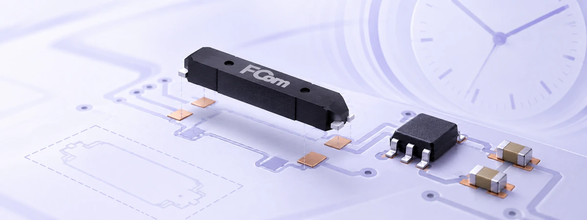
FCom FCT-6M is a 32.768 kHz tuning-fork crystal in a 6.9 × 1.4 × 1.3 mm SMD package. Published options include 6, 7, 9 and 12.5 pF load capacitance, with maximum ESR of 65 kΩ and an operating range of −40 to +85 °C.
These characteristics support evaluation for a narrow PCB area, but the smaller external dimensions do not prove pad compatibility. Obtain the controlled drawing and specification for the proposed ordering code. Compare terminal positions, solderable areas, orientation, maximum height and assembly tolerances.
Treat FCT-6M as a candidate until qualification is complete. If the land pattern or electrical network needs modification, document the change as a design migration. Epson’s notice does not identify FCT-6M as an endorsed alternative.
If a PCB revision is possible, review the wider FCom tuning-fork crystal range against the available area, electrical requirements and production process.
Qualification checklist before production release
- Freeze the baseline: capture the existing ordering code, schematic, PCB revision, capacitor values and oscillator settings.
- Review compatibility: approve the pin mapping, land-pattern overlay, load option, resistance limit, drive limit and temperature range.
- Test operating corners: repeat starts at minimum, nominal and maximum permitted supplies across the application’s temperature range, including backup supply where used.
- Measure timekeeping: record frequency error, start-up time, RTC current and recovery after relevant power transitions.
- Check production effects: compare results after reflow, cleaning and final enclosure assembly across multiple boards and suitable sample lots.
- Release a controlled configuration: document acceptance limits, approved components, firmware settings, supplier documentation and purchasing milestones.
Set sample counts and acceptance criteria before testing. Distinguish a true oscillator restart from a system reset that leaves the backup oscillator running.
Common questions
Is MC-146 already discontinued?
The cited notice identifies MC-146 M/F as NRND and provides planned lifecycle dates. Confirm current status for the full ordering code with Epson; NRND alone does not mean final shipment has occurred.
Can any 32.768 kHz crystal replace it?
No. Frequency is only one requirement. Mechanical fit, terminal connections, load capacitance, oscillator margin and drive limits must also match the design.
Can firmware calibration fix an unsuitable replacement?
Calibration can correct some timekeeping offset. It does not repair poor start-up margin, excessive drive, incompatible terminals or an unsuitable land pattern.
Is FCT-6M a guaranteed drop-in replacement?
No blanket guarantee applies. Confirm the exact component specification and validate it on the production board before approving interchangeability.
Request an MC-146 replacement review. Send the full MC-146 ordering code, MCU/RTC model, schematic, PCB footprint, target load capacitance, temperature range and annual volume to FCom@fujicrystal.com, or contact FCom to discuss candidate selection and qualification requirements.


