
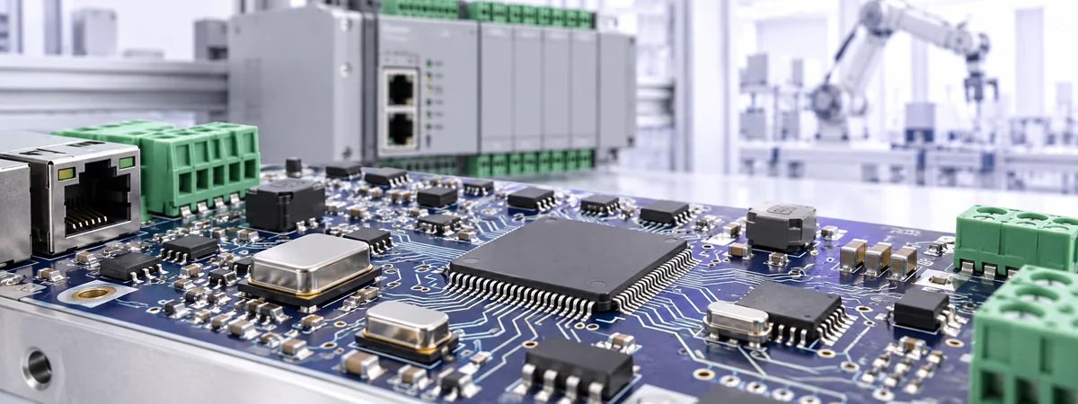
Industrial Control · Timing Selection
Industrial timing starts with the job each clock must perform. A controller reference, an interface clock, a wireless reference and an always-on RTC face different requirements for startup, frequency accuracy, noise and power.
FCom Fuji Crystal · Technical Guide
What is an industrial-grade crystal oscillator? It is an active quartz-based clock source specified for the intended industrial operating conditions. Selection depends on documented temperature, electrical and reliability requirements. The label alone does not guarantee low jitter, temperature compensation or suitability for every harsh environment.
What does industrial grade mean?
A quartz resonator uses the piezoelectric effect to couple electrical energy and mechanical vibration. In a crystal oscillator, an active circuit sustains oscillation and supplies a usable output. A passive crystal requires a compatible oscillator circuit in the MCU, RTC or other host device.
A common industrial operating range is −40°C to +85°C; extended-temperature options may reach +105°C or +125°C. These are selection categories, not universal ratings. Check the exact ordering code, guaranteed electrical limits and temperature definition in the datasheet. Storage temperature is not an operating specification.
Specify shock, vibration, humidity exposure and assembly conditions separately. An industrial temperature rating does not establish automotive qualification, medical-device compliance or a fixed service life. Likewise, mechanical survival and frequency stability during vibration are different requirements.
Choose the device against its documented limits and your validation plan. Frequency-stability definitions can include different combinations of temperature, supply, load and aging effects, so compare conditions as well as ppm values. [1]
Map the system into four timing domains
PLCs, gateways, motor controllers and measurement equipment may use several clock sources. Assign each source a role before selecting parts. A design does not necessarily need all four domains or a separate device for every function.
| Clock domain | Typical component | Primary checks |
|---|---|---|
| MCU / SoC reference | MHz quartz crystal with the host IC’s oscillator circuit | Load capacitance, ESR, drive level, startup margin and layout |
| Board and interface clocks | Packaged XO, with clock buffers where needed | Output compatibility, jitter, fanout, supply noise and sequencing |
| Wireless / GNSS reference | TCXO or VCTCXO when the frequency budget requires it | Temperature stability, phase noise, output waveform and tuning range |
| Always-on timekeeping | 32.768 kHz crystal with an RTC oscillator circuit | Backup current, startup, effective load, leakage and accumulated drift |
In a motion controller, the MCU reference supports control timing while an interface clock supports communication. An industrial gateway may add a wireless reference. A meter may retain a separate RTC supply so timestamps continue while the main processor is off.
Selection and integration checks for each domain
1. MHz crystals: validate the oscillator loop
Match frequency, load capacitance (CL), equivalent series resistance (ESR) and permitted drive level to the host IC. For a typical two-capacitor Pierce circuit, a first-order estimate is CL ≈ C1 × C2 ÷ (C1 + C2) + Cstray. Include pin and PCB parasitics according to the IC vendor’s model; do not count them twice.
Check startup margin at low supply voltage and temperature extremes. Keep the crystal loop compact, protect it from switching nodes, and follow the host IC’s grounding guidance. Select the footprint only after confirming that the required electrical margins are achievable.
2. XOs: match the receiver and distribution network
A packaged XO integrates the resonator, sustaining circuitry and output buffer. Confirm the receiving IC’s supported clock input, supply compatibility, logic thresholds and termination requirements. CMOS, LVDS and LVPECL outputs are not interchangeable.
Evaluate duty cycle, rise/fall time and jitter with the intended load. A source that drives one input successfully may require a fanout buffer for multiple loads. Check supply decoupling, return paths and power sequencing, including the behavior when a clock reaches an unpowered receiver.
3. TCXOs and VCTCXOs: control frequency error over temperature
A TCXO adds temperature compensation. A VCTCXO also provides voltage-controlled frequency adjustment. Consider these devices when the wireless or GNSS reference budget exceeds what a standard XO can deliver.
Separate initial tolerance, temperature stability, supply sensitivity and aging unless the datasheet provides an inclusive limit. Match the output waveform to the receiver. For a VCTCXO, confirm usable tuning range and control-voltage noise. Compare phase noise at specified offsets and integrated jitter over the same frequency band.
4. RTC crystals: protect the backup domain
A 32.768 kHz crystal is a passive reference for the RTC’s oscillator circuit. It does not keep time by itself; the RTC and its supply must remain active. Check CL, ESR and maximum drive level against the RTC requirements.
Validate cold startup, backup-supply transitions and leakage on the assembled board. Account for temperature dependence, aging and assembly stress when defining calibration intervals. A smaller package is useful only if startup margin and the power budget remain acceptable.
A practical board validation workflow
- Define the requirements: record each clock consumer, frequency, error limit, supply, output interface and operating temperature.
- Identify the main risk: startup failure, frequency drift, interface jitter, EMI coupling or backup-current limits.
- Shortlist compatible parts: compare guaranteed limits, ordering options, footprints and qualification documentation.
- Test the real PCB: cover cold and hot startup, supply corners, repeated power cycles, sleep/wake transitions and representative switching activity.
- Record acceptance evidence: measure frequency, startup time, receiver waveforms and current with documented loading and test conditions.
Use a suitable low-capacitance measurement method. Probing crystal pins can alter the oscillator loop. For buffered outputs, verify the signal at the receiving device as well as at the source.
Illustrative timekeeping budget: a constant 10 ppm frequency offset produces 86,400 × 10 ÷ 1,000,000 = 0.864 seconds per day of uncorrected time error. This calculation is not a product rating; changing temperature, calibration and synchronization affect the actual result.
Check service-life assumptions separately from initial approval. Aging specifications apply over stated periods and conditions; an MTBF figure is not a guaranteed operating lifetime for an individual component.
FCom selection guides and product families
Use the application guide to define the engineering checks, then review the corresponding family for candidate devices. Confirm the final part number against its individual datasheet.
| Domain | Application guide | Product family |
|---|---|---|
| MCU / SoC | SMD crystal selection | SMD crystal family |
| Board clocks | XO selection and integration | Clock oscillator family |
| Wireless / GNSS | TCXO / VCTCXO selection | TCXO / VCTCXO family |
| RTC timekeeping | 32.768 kHz crystal selection | RTC crystal family |
Frequently asked questions
Should an industrial controller use a crystal or an XO?
Use a crystal when the host IC’s oscillator circuit can meet the required startup and frequency margins. Consider an XO when a buffered clock or separate distribution source is needed. Verify external-clock input support before changing architectures.
Does industrial grade mean temperature-compensated?
No. Temperature grade defines an operating range. Temperature compensation is a separate function provided by a TCXO or VCTCXO. A standard industrial XO may be sufficient if its guaranteed stability meets the system budget.
Does a lower ppm value guarantee lower jitter?
No. Frequency error and short-term edge variation are different metrics. Specify both when the application requires them, and compare jitter under matching measurement conditions.
Will an RTC crystal keep time when the system is off?
Only if the RTC oscillator and counter retain power, normally through a backup supply. The crystal alone cannot maintain timestamps. Validate backup current and supply switching at board level.
How long will an industrial oscillator last?
There is no universal lifetime. Review operating conditions, aging limits, reliability documentation and the intended service period. Environmental testing and long-term accuracy requirements should be part of the component approval plan.
Discuss your industrial timing requirements
Send FCom your clock consumer IC, target frequency, operating temperature, supply rails, output format, accuracy or jitter budget, package limits and main validation concern. Email FCom@fujicrystal.com to discuss suitable options.
Technical reference
[1] SiTime: Timing Terminology Glossary — operating temperature, frequency stability, aging and jitter definitions. FCom application and product-family resources are linked above; individual device datasheets govern product specifications.


