
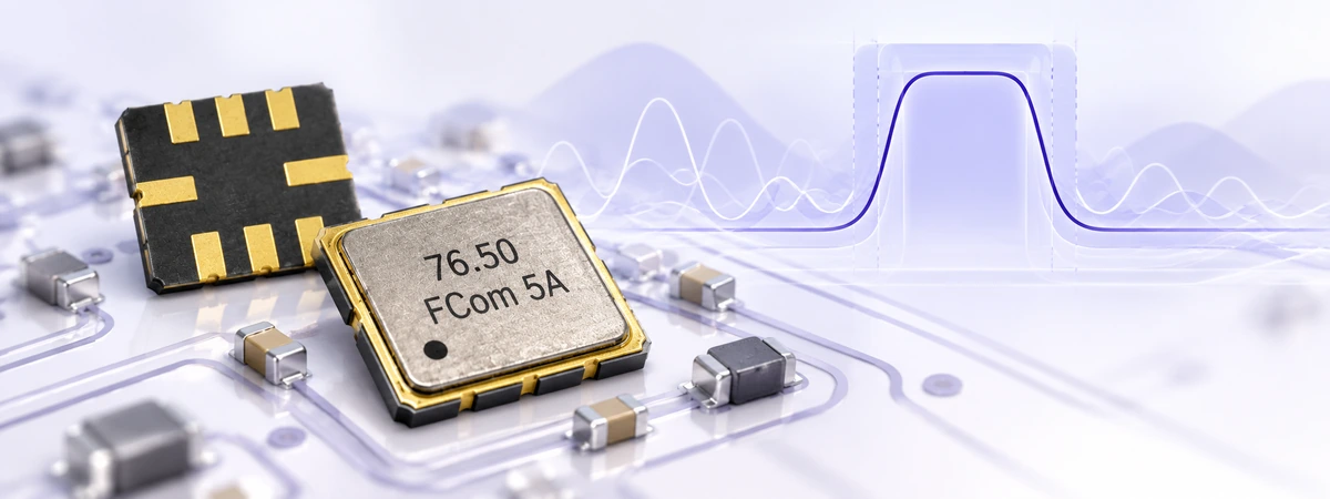
RF & IF Design · SAW Filter Selection
Choosing a SAW filter starts with the signal your system must preserve and the interference it must reject. Center frequency is only the first screening criterion. The final choice must also satisfy passband loss, bandwidth, rejection, impedance, temperature and power requirements on the actual PCB.
FCom Fuji Crystal · Technical Guide
1. Define the system requirements
A surface acoustic wave filter uses piezoelectric conversion between electrical signals and acoustic waves to produce a frequency-selective response. Its suitability depends on where it sits in the RF or IF chain and the signals present at that point.
- Wanted spectrum: record channel edges, modulation bandwidth, tuning range and frequency uncertainty.
- Blocker spectrum: identify adjacent services, image frequencies, local-oscillator leakage and coupled transmitter signals, including their input levels.
- Interface: identify source/load impedance, balanced or unbalanced ports and the available matching-component space.
- Environment: define operating temperature, RF power, duty cycle, assembly constraints and required qualification.
For GNSS receivers, prioritize the wanted satellite bands and the loss/blocking trade-off. For sub-GHz radios, specify the actual regional channels. For IF filtering, use the receiver frequency plan and demodulation bandwidth. An application label alone does not establish compatibility.
2. Compare the electrical specifications
Center frequency and bandwidth
Use the datasheet definition of nominal or center frequency; it is not necessarily the frequency of minimum insertion loss. Check the complete wanted band over the specified temperature range.
| Term | Meaning | Selection check |
|---|---|---|
| 1 dB / 3 dB bandwidth | Frequency span between crossings at the stated attenuation level. | Confirm whether the level is relative to minimum loss or an absolute reference. Do not interchange 1 dB and 3 dB values. |
| Usable passband | Frequency interval over which specified performance limits apply. | Check maximum loss, ripple and other limits across the entire interval and stated operating conditions. |
| Shape factor | Ratio of bandwidths at two defined attenuation levels, such as BW40 dB / BW3 dB. | Compare identical levels and references. A lower ratio indicates steeper skirts for that definition. |
Illustrative bandwidth budget: a 400 kHz occupied signal with ±50 kHz frequency uncertainty needs 500 kHz of coverage. Adding 50 kHz of design reserve at each edge gives:
Required coverage = 400 + 2 × 50 + 2 × 50 = 600 kHz
This is a design example, not a product specification. Verify the required loss and ripple across this span. Account for filter tolerance and thermal shift without adding allowances twice when already included in guaranteed limits.
Insertion loss, ripple and group delay
Budget the maximum insertion loss across the wanted band, including matching and PCB losses. A typical minimum-loss value is insufficient. Ripple describes amplitude variation; group-delay variation describes unequal delay across frequency and can affect modulation quality. Evaluate both over the occupied signal bandwidth. [1]
Under matched conditions at the reference temperature, a passive filter before the first amplifier adds approximately its insertion loss in dB to the receiver noise figure. Moving it after an LNA reduces that noise penalty, but leaves the LNA exposed to blockers. Choose placement using both sensitivity and overload requirements.
Stopband attenuation and impedance
Write rejection requirements at specific frequencies or across complete bands. Confirm whether attenuation is absolute or measured relative to passband transmission. A deep notch at one frequency does not guarantee rejection throughout a blocker band.
Do not assume every SAW filter has 50 Ω ports. Some require complex terminations, higher impedances or differential connections. Check both port impedances, matching networks and return loss. Compare S-parameters using the same reference impedance and calibration plane.
3. Follow a practical selection workflow
- Draw the mask. Mark wanted-band edges and allowable loss, plus each rejection band and its attenuation target.
- Shortlist frequencies. Select candidate variants whose specified passbands cover the complete signal and tolerance budget.
- Compare guaranteed limits. Check loss, ripple, rejection and temperature conditions together; treat typical curves as supporting information.
- Check the interface. Confirm pinout, source/load terminations, matching values and available PCB area.
- Check operating limits. Verify RF power, temperature, DC restrictions, reflow conditions and documented qualification for the exact part.
- Validate samples. Measure the assembled circuit, then test receiver sensitivity, blocking and modulation performance.
Power capability depends on frequency, temperature and signal conditions. Do not extrapolate a short-pulse rating to continuous operation or assume a receive filter can be used after a power amplifier. The selection principles in RF360 Application Note 19 provide additional context. [2]
4. Shortlist FCom SAW filter families
Use these family pages to identify candidates, then request the exact variant datasheet. The ranges below describe different models within each family; they are not continuous passbands or tuning ranges of a single device.
| Family | Listed frequency coverage | Package footprint | Initial screening |
|---|---|---|---|
| FSF-5050 | 76.5–1000 MHz | 5.0 × 5.0 mm | IF, VHF/UHF and sub-GHz candidate variants. |
| FSF-3030 | 300–2605 MHz | 3.0 × 3.0 mm | RF candidate variants, including selected GNSS and wireless bands. |
Explore the FCom SAW filter catalog for additional package options. Frequency coverage does not establish availability at every intermediate frequency. Confirm bandwidth, loss, rejection, impedance and ratings for the complete ordering code.
5. Validate matching, layout and performance
Start with the recommended footprint and matching circuit. Keep RF connections short, maintain the intended transmission-line impedance and provide low-inductance ground returns. Separate input and output routing to reduce coupling that can bypass the filter. Include ESD-device capacitance in the circuit evaluation.
Use a calibrated VNA to measure S21, S11, S22 and group delay. Remove fixture effects when necessary, maintain adequate stopband measurement dynamic range and repeat critical measurements across temperature. Finally, evaluate the complete receiver with representative wanted signals and blockers.
For implementation details, see How to Measure SAW Filters and the SAW Filter PCB Layout and ESD Protection Guide.
6. Frequently asked questions
Is the narrowest SAW filter always the best choice?
No. It must pass the complete signal, including frequency uncertainty, while meeting loss, ripple and delay requirements. Excessively narrow filtering can distort the wanted signal.
Why is measured insertion loss higher than the datasheet value?
Check calibration, fixture loss, reference impedance, matching components, grounding and temperature. Compare against the same frequency interval and test conditions before judging the device.
Can filters with the same frequency and package be interchanged?
Only after verifying pinout, footprint, impedance, bandwidth, rejection, power limits and assembly conditions. Matching components may need revision, followed by board-level qualification.
When should I evaluate BAW or LC alternatives?
Consider alternatives when available SAW variants cannot meet the combined frequency, bandwidth, temperature, power or cost requirements. BAW can address demanding higher-frequency applications; LC networks offer different implementation trade-offs. Compare actual devices against the same mask. [3]
Discuss your SAW filter requirements with FCom
Send your frequency mask, maximum passband loss, rejection targets, source/load impedance, temperature range, input power and package constraints to FCom@fujicrystal.com. Include the block diagram and expected volume so we can review suitable standard variants or assess a custom requirement.
Technical references
- Abracon: SAW Filters: Performance Characteristics (Part I) — acoustic operation and electrical performance parameters.
- RF360, hosted by Qualcomm: How to Choose the Optimal SAW Filter, Application Note 19 — system requirements and operating-limit checks.
- Qorvo: BAW vs. SAW RF Filters — technology selection considerations.


