
Oscillator Selection
Crystal and MEMS oscillators both provide reference clocks. Choosing between them requires a comparison of frequency accuracy, phase noise, jitter, power and performance in the intended operating environment.
FCom Fuji Crystal · Technical Guide
How crystal and MEMS oscillators work
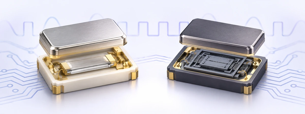
A quartz crystal oscillator combines a piezoelectric quartz resonator with a sustaining circuit and an output stage. A silicon MEMS oscillator uses a micromachined mechanical resonator with supporting electronics, often including temperature compensation and frequency synthesis. Both depend on mechanical resonance; their materials and circuit architectures differ. [1]
A passive crystal needs an external oscillator circuit, often inside a microcontroller. An active oscillator takes a power supply and delivers a clock output. Compare complete clock solutions: a packaged MEMS oscillator is not a direct substitute for a passive crystal connected between two oscillator pins.
The term “MEMS crystal oscillator” can be misleading. For silicon MEMS timing devices, use “MEMS oscillator” to distinguish the resonator technology from quartz.
Crystal vs MEMS: key differences
| Criterion | Quartz oscillator | MEMS oscillator |
|---|---|---|
| Frequency accuracy | Depends on compensation, calibration, temperature and aging. | Depends on compensation, calibration, temperature and aging. |
| Phase noise and jitter | Strong options for low-noise references; inspect the complete noise spectrum. | Low-jitter options are available; inspect the complete noise spectrum. |
| Power | Varies by frequency and architecture; oven control adds power demand. | Varies by synthesis, compensation and output architecture. |
| Shock and vibration | Evaluate acceleration sensitivity and package qualification. | Often a strength; verify the specified operating tests. |
| Frequency flexibility | Fixed-frequency, tunable and programmable designs exist. | Programmable frequency options are common. |
| Size and compatibility | Compact standard packages are available. | Compact standard packages are available; check electrical compatibility. |
This table summarizes selection considerations, not guaranteed specifications. Manufacturer portfolios include both low-power and low-jitter quartz and MEMS devices. [2]
Frequency stability: read what the ppm figure includes
A temperature-stability specification does not necessarily describe total frequency error. Check initial tolerance, temperature drift, supply variation, output loading and aging. Determine which terms are included in the stated limit before building a worst-case budget; do not count an included term twice. [3]
Frequency error (Hz) = nominal frequency (Hz) × error (ppm) ÷ 1,000,000
Illustrative example: a 25 MHz clock with a ±20 ppm error has a frequency offset of up to ±500 Hz. A constant 20 ppm timebase error accumulates approximately 1.728 seconds per day without correction.
Compare equal temperature ranges and aging intervals. For synchronization and holdover, also assess thermal transients, short-term stability and the system’s calibration strategy. A room-temperature measurement alone does not establish performance across the application environment.
Phase noise and jitter: compare the same measurement
Phase noise describes spectral noise at offsets from the carrier, usually in dBc/Hz. Integrated RMS phase jitter expresses the corresponding timing variation over a defined offset-frequency band. Period jitter and cycle-to-cycle jitter are different measurements and cannot be substituted directly. [4]
For a fair comparison, match carrier frequency, integration limits, filtering, supply voltage, output format and load. Check whether spurs are included and whether values are typical or guaranteed maximums. The frequently quoted 12 kHz–20 MHz band is appropriate only when it matches the receiving interface’s requirement.
Quartz can be attractive for demanding close-in noise requirements, but “quartz always has lower jitter” is too broad. Published comparisons evaluate particular devices and generations; later MEMS designs can produce substantially different results. Review the full phase-noise curve and system clock path. [1] [5]
Power consumption and start-up time
Compare current at the same frequency, supply voltage, output load and operating mode. An unloaded current figure is not equivalent to consumption while driving the required clock input. Check external termination power as well as oscillator supply current.
For duty-cycled equipment, include active current, standby current, wake-up energy and the time needed to reach usable frequency accuracy. Output enable may only disable the output buffer; it does not necessarily stop the internal oscillator. Confirm the selected device’s behavior.
Quartz TCXOs compensate temperature-induced drift, while quartz OCXOs use thermal regulation and require a warm-up allowance. Neither a compensation label nor an oven automatically guarantees the lowest jitter. Battery-powered 32.768 kHz designs should compare the complete RTC or oscillator solution against the required timekeeping accuracy. [6]
Shock, vibration and electrical noise
MEMS resonators can offer low sensitivity to mechanical disturbance, making them useful candidates for equipment exposed to movement or vibration. However, surviving a shock test and maintaining low phase noise during vibration are separate requirements. Compare test profiles, acceleration, frequency range and measured clock behavior. [7]
Supply ripple can also degrade timing performance. Evaluate the device on the intended power rail, with nearby converters and digital loads operating. Follow the manufacturer’s decoupling and layout guidance, and assess clock quality at the receiver. [8]
A practical oscillator selection checklist
- Define the clock input: frequency, voltage, output format, duty cycle, loading and enable behavior.
- Set separate budgets: total frequency error, phase noise, jitter and time to valid output.
- Specify the environment: operating temperature, thermal changes, vibration, shock and supply noise.
- Shortlist equivalent devices: compare guaranteed limits and datasheet conditions, package height, pinout and land pattern.
- Validate the complete system: test cold start, wake-up, thermal operation and clock quality at the receiving device.
For RF and precision measurement, prioritize the required noise offsets and frequency accuracy. For high-speed digital interfaces, use the receiver’s jitter limits and filtering rules. For portable products, evaluate energy per operating cycle. For industrial equipment, include performance under mechanical and electrical disturbance.
Programmable frequency can simplify variants, but availability, price and qualification depend on the exact ordering code. A design may use different clock technologies for different subsystems when their requirements differ.
Common questions
Can a MEMS oscillator replace a quartz oscillator?
Sometimes. Confirm frequency, pinout, supply, output levels, enable function, load, start-up and timing specifications. A matching package alone does not establish interchangeability.
Is MEMS always smaller or more power-efficient?
No. Both technologies offer compact devices. Compare the complete solution’s footprint and operating power under matching conditions.
Does tighter ppm stability mean lower jitter?
No. Frequency accuracy and edge timing variation describe different aspects of a clock. Specify and verify both.
Should I choose an XO, TCXO, VCXO or OCXO?
Start from the required function: a clock source, temperature compensation, voltage-controlled tuning or oven-controlled stability. Check the actual noise, power and environmental specifications rather than treating these categories as a universal performance ranking.
Discuss your timing requirements with FCom. Send your frequency, supply voltage, output format, package, temperature range, accuracy and jitter requirements to FCom@fujicrystal.com. Include the existing part number when evaluating a replacement.
Technical references
Manufacturer comparisons describe the devices and test conditions in each publication. They should not be generalized to every quartz or MEMS oscillator.
- Epson: Comparison of Crystal Oscillator and Si-MEMS Oscillators (PDF) .
- Microchip: MEMS and Crystal Oscillators .
- SiTime AN10039: TCXO Frequency Stability and Frequency Accuracy Budget .
- SiTime AN10007: Clock Jitter Definitions and Measurement Methods .
- SiTime: Comparison of Quartz Crystal Oscillators and Silicon MEMS Oscillators (PDF) .
- Microchip: Oscillators (PDF) .
- SiTime: Shock and vibration performance .
- SiTime: Power supply noise and oscillator performance .


