
Timing design & troubleshooting
Understand slow startup, find the cause of missing clocks, and verify reliable operation on your board.
FCom Fuji Crystal · Technical Guide
A crystal oscillator needs time to build a usable signal after power-up or restart. Slow or failed startup can result from inadequate oscillation margin, unsuitable loading, supply problems, assembly defects or incorrect clock configuration. First identify the circuit type and the event you are measuring.
What does oscillator startup time mean?
Define both endpoints before comparing results. A datasheet may measure from a specified supply threshold to a valid output; your system may measure from a wake command to the first usable clock. These intervals can include different delays.
- Crystal with an MCU or ASIC: the passive resonator works with an amplifier inside the IC. Oscillation buildup and the IC’s clock qualification delay are separate events.
- Packaged oscillator: check its power-on, standby recovery and output-enable specifications individually. Output enable may only control the output buffer while the oscillator continues running.
- OCXO: the appearance of output transitions does not establish that the oven has reached its specified frequency accuracy. Check the separate warm-up requirement.
A downstream PLL may need additional time to lock. Where stages overlap, use the actual clock sequence rather than simply adding every published delay.[1]
Why a crystal oscillator takes time to start
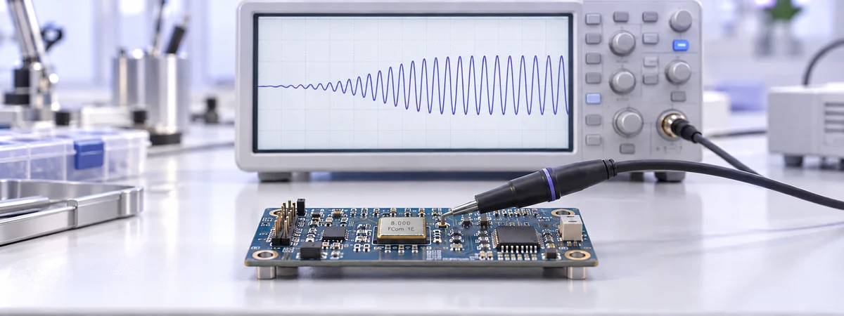
At startup, a small electrical disturbance is reinforced by the active circuit near the intended resonance. The signal grows until circuit limiting establishes its operating amplitude. The circuit must replenish resonator losses throughout this process.[2]
Growth depends on the complete circuit: amplifier behavior, crystal losses, loading and operating conditions. Resonant frequency or Q alone cannot predict a reliable startup time.
ST’s AN2867 gives illustrative examples of a few milliseconds for MHz crystal circuits and 1–5 seconds for 32.768 kHz circuits. These are not universal limits or guarantees for FCom products. Use the applicable IC or oscillator specification and measured board results.[3]
Match the symptom to the next check
Separate a missing source clock from a clock that is present but has not reached the processor or peripheral.
| Observed symptom | Possible cause | Next check |
|---|---|---|
| No module output | Supply, enable state, wrong pinout or damaged part | Measure the supply at the device and verify pin functions. |
| Clock present, system inactive | Reset, clock routing, bypass mode or PLL configuration | Read clock and reset status; verify the selected source. |
| Intermittent cold starts | Marginal circuit operation or supply behavior at temperature | Repeat with temperature soak and capture the local supply. |
| Failure after assembly or handling | Solder defects, contamination or mechanical damage | Inspect the package, pads and connections; compare a known-good board. |
| Behavior changes when probed | Added capacitance or coupled interference | Compare against a buffered clock or supported status signal. |
| Failure only after sleep | Different restart sequence or insufficient qualification time | Check which clock domains stop and how firmware restores them. |
Configuration errors can also leave the MCU running from a fallback internal clock. Confirm the active source rather than assuming that successful code execution proves the external oscillator is working.[4]
Measure startup without changing the result
- Set a repeatable trigger. Capture the specified supply threshold or enable transition, together with the output or a supported clock-status indication.
- Define a valid endpoint. Check amplitude, frequency and continuity as required by the receiving circuit. The first visible edge alone is insufficient.
- Prefer a buffered observation point. Direct probing of crystal pins adds loading and can change startup behavior. Follow the IC vendor’s recommended probing method.[5]
- Identify what a status signal means. A ready flag or firmware GPIO can include detection, polling and software delays. It is not automatically a direct measurement of resonator buildup.
- Repeat genuine restarts. Distinguish a discharged power cycle from a reset that leaves the oscillator running. Record restart conditions alongside the waveform.
Apply corrections to the actual failure mechanism
Check supply, assembly and configuration first
Verify the required voltage, local decoupling, ground connection and control-pin states. Inspect solder joints and confirm that the installed part matches the schematic. A crystal-input mode and an external-clock bypass mode are not interchangeable. Check reset behavior before replacing a resonator.
Match the crystal to the amplifier
For a discrete crystal circuit, verify frequency range, vibration mode, maximum ESR, load capacitance and drive rating. Calculate the effective load using external capacitors, pin capacitance and board parasitics; include internal programmable loading where applicable.
Reducing capacitor values may improve one startup result while shifting frequency. Increasing drive can exceed the crystal’s permitted operating level. Make changes within the IC and crystal requirements, then recheck both startup and steady operation.[2]
Verify margin and layout
Assess negative-resistance or gain margin using the IC manufacturer’s procedure. There is no single safety factor for every oscillator. For example, ST’s AN2867 distinguishes HSE and LSE requirements; apply the guidance for the actual device.[3]
Keep sensitive crystal connections short and follow the vendor’s grounding and routing recommendations. Check leakage from contamination and interference from nearby switching signals. Revalidate after cleaning, rework or layout changes.[5]
A longer firmware timeout can accommodate a healthy but slow circuit. It does not repair a circuit that intermittently fails to oscillate. Use startup assistance only when the IC manufacturer documents it.
Verify the result across operating conditions
Build a test matrix covering supply limits, expected ramp profiles, temperature extremes, power-on and sleep recovery. Include multiple boards and component lots where practical. Record the longest observed delay and any failures, not just an average.
Check frequency and drive level after the change. A part that starts quickly but runs outside its loading or drive requirements is not a successful replacement.
For systems with strict wake-up deadlines, compare restarting the source with keeping a reference running and gating its output. Evaluate the complete power budget. A TCXO or OCXO should be selected against its documented timing and stability requirements, not assumed to be a faster solution.
Common questions
Does the crystal determine startup time by itself?
No. A passive crystal operates with an active circuit. The chosen IC, loading, supply and board implementation all matter.
Can I fix slow startup by extending the delay?
Only if the circuit reliably becomes valid within the allowed interval. Investigate intermittent failures instead of hiding them with a longer wait.
Is output-enable time the same as power-on startup?
No. A device may keep its oscillator running while disabling only the output. Check the pin function and timing definition in its datasheet.
Does an OCXO output mean warm-up is complete?
No. Output availability and frequency settling are separate requirements. Verify the specified warm-up accuracy under the stated conditions.
FCom timing device support
For selection or troubleshooting support, send the part number,
IC model, schematic, supply conditions, temperature range and
measured startup waveforms to
FCom@fujicrystal.com.
Include the required time to a valid clock and whether the issue
occurs at power-on or after sleep.
Technical references
- Microchip — PIC32 Oscillator Start-up Timer
- Microchip AN826 — Crystal Oscillator Basics and Crystal Selection (PDF)
- STMicroelectronics AN2867 — Guidelines for oscillator design (PDF)
- Microchip — 8-bit PIC and AVR MCU Design and Troubleshooting (PDF)
- Texas Instruments SLAA322D — MSP430 32-kHz Crystal Oscillators (PDF)


