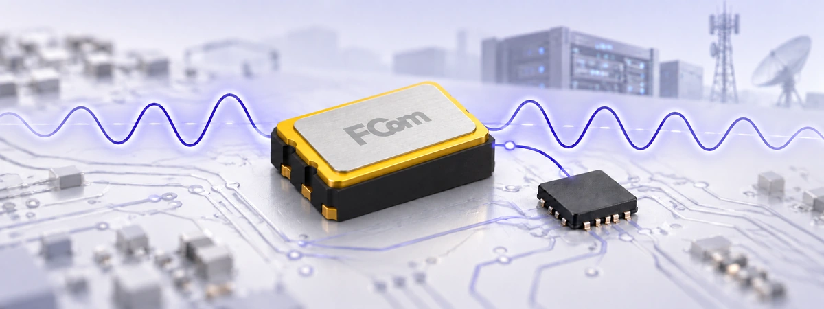
Quartz Crystal Technology · Manufacturing
Making an SMD quartz crystal involves more than cutting a small piece of quartz and enclosing it in a package. Material quality, crystal orientation, electrode geometry, mounting stress and sealing all contribute to the finished component’s behavior. Understanding these relationships helps engineers specify a crystal and helps buyers ask useful questions about production quality.
FCom Fuji Crystal · Technical Guide
How are SMD quartz crystals made? A typical route starts with synthetic quartz, followed by oriented cutting, blank processing, electrode formation, mounting, frequency adjustment, sealing and inspection. This guide describes common industry methods for passive MHz SMD crystal units. Exact materials, equipment and process sequences depend on the product.
Start with synthetic quartz and the correct cut
Modern electronic crystal units commonly use synthetic single-crystal quartz. In hydrothermal growth, quartz nutrient dissolves in a hot, pressurized solution and recrystallizes on seed crystals inside an autoclave. Natural quartz may supply the nutrient, but this does not make the finished resonator blank a directly cut natural gemstone. Seed quality, inclusions and growth defects matter to subsequent processing. [1]
A crystal unit is a passive resonator. An external oscillator circuit supplies the energy needed to sustain oscillation; the unit itself does not provide a powered CMOS clock output.
For many MHz products, the quartz is oriented for an AT-cut thickness-shear mode. Cut angle affects frequency-versus-temperature behavior, while blank thickness strongly influences resonance frequency. These relationships should not be transferred directly to 32.768 kHz tuning-fork crystals, which use a different vibration mode. [2]
From quartz blank to sealed SMD component
1. Cut, lap and shape the blank
Oriented material is sliced and processed into blanks. Grinding, lapping and polishing bring the quartz toward its required dimensions and thickness. For a given AT-cut thickness-shear mode, reducing the vibrating thickness raises frequency. Blank shape and edge processing also influence vibration behavior; a mirror-like appearance alone does not establish electrical quality. [4]
2. Prepare the surface and form electrodes
Chemical etching can remove surface damage introduced by machining, followed by cleaning to remove residues. Metal electrodes are then formed by methods such as vacuum evaporation or sputtering. Their pattern and thickness are controlled parts of the resonator design. [3]
3. Mount the resonator
The electrode-bearing blank is attached to package terminals using a suitable support and interconnection method. Conductive adhesive is a common approach. The attachment must provide electrical contact while allowing the intended vibration. Do not assume that an ordinary passive crystal requires the thermosonic ball-bonding sequence used for semiconductor dies. [3]
Mounting is also a materials-control step. Adhesive curing, thermal expansion differences and residual stress can influence frequency over time. Clean processing and controlled curing help manage these effects. [5]
4. Adjust frequency under defined conditions
Fine adjustment compensates for manufacturing variation after coarse blank processing. One established method measures frequency while adding a controlled amount of metal to the electrode. Added mass generally lowers resonance frequency. This illustrates the adjustment principle; the equipment and sequence vary with package and process. [4]
The acceptance target must specify whether frequency is measured at series resonance or with a stated load capacitance, together with temperature and drive level. Matching the printed MHz value without matching these conditions is not an equivalent test. [2]
5. Seal the cavity
Hermetic package designs isolate the resonator from moisture and contamination. Depending on construction, sealing may use seam welding, glass or a gold-tin alloy. The cavity may be evacuated or contain a controlled gas atmosphere. No single sealing method applies to every SMD crystal. [3]
6. Inspect and prepare for assembly
Electrical and visual checks establish acceptance against the product specification. The released device must also match its drawing, terminal definition and packing requirements. Tape-and-reel orientation, marking and lot identification should be agreed before automated PCB assembly.
Materials and miniaturization: established methods, specific trade-offs
The quartz blank, electrode film, mounting material and enclosure perform different functions. A ceramic package does not mean that the vibrating element is a ceramic resonator. Likewise, electrode material should not be assumed from the external lid color or terminal finish.
Miniaturization can involve changes to the resonator structure as well as the package. Epson documents photolithographic processing and inverted-mesa AT-cut structures: a thinner vibrating region supports higher fundamental frequencies while a thicker surrounding region retains mechanical strength. This is an example of an established manufacturer-specific technology, not a process used by every SMD crystal supplier. [6]
Smaller size alone does not prove lower ESR, better aging or tighter temperature stability. Compare the complete specification and circuit performance. For a proposed material or package change, request evidence of its effect on the parameters your application actually needs.
Internal contamination can transfer material to or from the resonator, while mounting and material stresses can relax with time. Both mechanisms can contribute to aging. A clean cavity and a suitable mounting system therefore matter alongside initial frequency adjustment. [5]
Separate production measurements from reliability qualification
A useful quality review identifies what is measured on each unit, what is checked by lot sampling and what is established through qualification. Avoid assuming that every shipped crystal undergoes every environmental or mechanical test.
| Check | What it establishes | Conditions to record |
|---|---|---|
| Frequency tolerance | Deviation from nominal at the reference condition. | Temperature, load or series-resonance condition, drive level and fixture. |
| ESR and resonance behavior | Loss and intended-mode behavior relevant to oscillator operation. | Measurement method, excitation level and acceptance limits. |
| Frequency versus temperature | Frequency movement across the specified operating range. | Reference temperature, range, stabilization and test coverage. |
| Aging | Frequency change over a stated time interval. | Storage or operation conditions, duration and any acceleration model. |
| Package and environmental reliability | Evidence relevant to sealing, assembly and service stresses. | Applicable leak, reflow, thermal, humidity, shock or vibration tests; sample size and pass criteria. |
Finished-device performance still requires validation in the application. Excessive drive can damage a crystal, insufficient oscillator gain can prevent startup, and incorrect load capacitance can shift frequency. Follow the selected component’s limits rather than adopting a generic drive-power value. [7]
What engineering and purchasing teams should request
- A controlled specification: complete part number, revision, nominal frequency, load capacitance, mode, ESR, drive level, tolerance, temperature stability and aging conditions.
- Assembly information: package drawing, pad assignment, land pattern, approved reflow profile, cleaning guidance and packing orientation.
- Quality evidence: an agreed inspection plan, relevant qualification results and the lot information needed for traceability.
- Change control: notification expectations for changes to materials, package construction or manufacturing location.
- Circuit validation: startup, frequency accuracy and drive-level checks on the actual IC and PCB.
Use these requests to connect manufacturing knowledge with measurable acceptance criteria. A general process description supports technical discussion; the approved product documents define what is supplied.
Frequently asked questions
Are SMD quartz crystals normally made from natural quartz?
Electronic resonators commonly use synthetic quartz grown under controlled conditions. Natural quartz can serve as growth nutrient; the resonator blank is then processed from the grown crystal.
Does frequency trimming remove temperature drift?
No. Initial frequency adjustment and temperature behavior are different characteristics. Cut orientation and resonator design remain important even after frequency is adjusted at the reference condition.
Can every crystal be ultrasonically cleaned after PCB assembly?
No. Cleaning compatibility depends on the device and process. Ultrasonic energy can affect or damage crystal devices; obtain the selected product’s handling guidance and validate the proposed cleaning conditions. [7]
Does hermetic sealing eliminate aging?
No. Sealing limits exposure to the external environment, but internal contamination and stress relaxation can still cause frequency movement. Use the specified aging limit and its stated conditions.
Discuss your SMD crystal requirements with FCom
Send your target frequency, IC or chipset, load capacitance, package, temperature range and frequency-error budget to FCom@fujicrystal.com. Include assembly constraints and the qualification documentation your project requires so we can review the appropriate specification with you.
Technical references
- NDK: Synthetic quartz growth and material quality
- Epson: Basic Knowledge of Crystal Unit
- NDK: How Crystal Units Are Manufactured
- IQD: Quartz blank, electrode and adjustment examples (HC49 construction)
- IQD: Quartz Crystal Ageing (PDF)
- Epson: High-frequency crystal processing and inverted-mesa structures (PDF)
- Epson: Handling Precautions