
FSF-5050 Series · SAW Bandpass Filter
743 MHz SAW Bandpass Filter
FSF-5050-743M
Narrowband RF filtering for 743 MHz receiver paths, with a specified 740–746 MHz passband in a 5.0 × 5.0 mm surface-mount package.
Key Features
Define the Passband and Interface
Specified Passband
740–746 MHz
Specified passband with a 6 MHz span. This is not a 3 dB bandwidth specification.
Insertion Loss
2.6 dB typ.
4.5 dB maximum over 740–746 MHz. Allow for filter loss in the receiver gain budget.
Amplitude Ripple
0.7 dB typ.
Over 740–746 MHz. Maximum not separately stated in the supplied table.
The specified passband 740–746 MHz is a frequency range, not the 3 dB bandwidth. A 3 dB bandwidth is not specified in the supplied datasheet.
Electrical Specifications
Six Key Selection Parameters
Electrical reference temperature: 25 °C. The documented test setup uses a 50 ohm source and a 50 ohm load with direct connection.
Scroll horizontally to view all columns.
| Parameter | Min. | Typ. | Max. | Unit | Definition / condition |
|---|---|---|---|---|---|
| Center frequency | — | 743.0 | — | MHz | Typical center frequency |
| Specified passband | — | — | — | MHz | 740–746 MHz; span 6 MHz |
| Insertion loss | — | 2.6 | 4.5 | dB | Over 740–746 MHz |
| Amplitude ripple | — | 0.7 | — | dB | Over 740–746 MHz; maximum not separately stated |
| 3 dB bandwidth | — | — | — | MHz | Not specified |
| Operating temperature | −10 | — | +60 | °C | Operating limits; not an electrical test condition |
— = not specified in that limit column. The passband range is stated separately; it is not a typical bandwidth value. A 6 MHz passband span does not define the 3 dB bandwidth. Storage range is −40 to +85 °C. Typical values are for design guidance; consult the FCom datasheet and confirm applicable limits for your design.
Typical Applications
Filtering within a 743 MHz RF Signal Path
UHF Receiver Filtering
Bandpass filtering for a receiver path whose wanted signal fits within the specified 740–746 MHz passband. Check the required signal bandwidth and permitted insertion loss.
Receiver Preselection
Evaluate the filter ahead of subsequent receiver stages to limit unwanted out-of-band energy. Confirm rejection and system noise performance for the intended blockers.
RF Test and Measurement
Frequency-selective filtering in a 743 MHz measurement path. Account for passband loss and ripple when assessing the complete setup.
Integration Notes
Start with the Documented Test Conditions
Source and Load
50 ohms each in the reference test setup. These values do not specify the device input or output impedance.
Matching and Layout
Evaluate the actual source, load, interconnect and grounding. Direct connection in the test setup does not guarantee the same response in every PCB implementation.
Temperature
Operating range −10 to +60 °C; storage range −40 to +85 °C. Do not extend the 25 °C typical electrical values to the full operating range.
Release Checks
Verify bandwidth definition, acceptable loss and ripple, blocker conditions and terminal orientation before finalizing the design.
Package & Pin Assignment
Compact 8-Terminal SMD Package
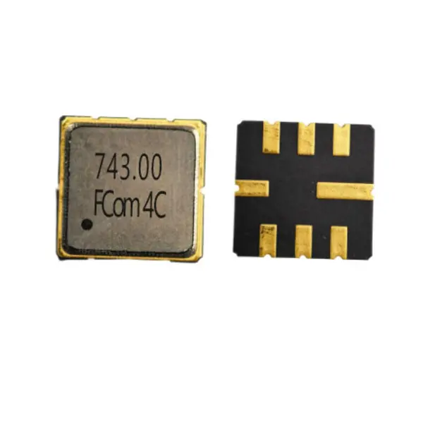
Use the mechanical drawing in the FCom datasheet to check pad numbering, dimensions and orientation. The product photograph is for identification, not a PCB footprint.
- Body dimensions
- 5.0 × 5.0 mm
- Maximum height
- 1.5 mm
- Package type
- 8-SMD, no lead
Contact FCom to discuss other pin configurations.
| Pin(s) | Function |
|---|---|
| 2 | Input |
| 6 | Output |
| 1, 3, 5, 7 | Ground |
| 4, 8 | Case ground |
Selection and Design-In Support
Define the Conditions That Matter to Your Design
Include your signal frequency range, required bandwidth definition, source and load requirements, operating temperature, sample quantity and estimated usage when contacting FCom. Use FSF-5050-743M as the model reference and confirm the complete ordering code before placing an order.
The model designation alone is not a confirmed complete ordering code.
Engineering Questions
Frequently Asked Questions
Is the 6 MHz passband span the 3 dB bandwidth?
No. The specified passband is 740–746 MHz, a span of 6 MHz. The 3 dB bandwidth is not specified in the supplied datasheet and must not be inferred from this range.
Does the filter have a specified 50 ohm device impedance?
The documented test setup uses a 50 ohm source and a 50 ohm load with direct connection. The device input and output impedances are not specified. Evaluate performance with the actual source, load and PCB layout.
Which terminals are used for the signal and ground?
Pin 2 is the input and pin 6 is the output. Pins 1, 3, 5 and 7 are ground terminals; pins 4 and 8 are case ground. Confirm terminal orientation against the FCom package drawing before PCB release.
What temperature conditions apply?
The operating range is −10 to +60 °C and the storage range is −40 to +85 °C. The electrical reference temperature is 25 °C; typical electrical values are not guaranteed across the full operating range.
What information should I include in an inquiry?
Include FSF-5050-743M, the required signal frequency range and bandwidth definition, source and load requirements, temperature range, sample quantity and estimated usage. Confirm the complete ordering code with FCom before ordering.