
FSF-5050 Series · SAW Bandpass Filters
604.5 & 609.9 MHz SAW Bandpass Filters
FSF-5050-604M5 / 609M9
Two RF/IF filter models in a 5.0 × 5.0 mm SMD package, with distinct bandwidth definitions and operating temperature ranges. Compare by center frequency, loss at the center frequency and the ripple limits that apply to each model.
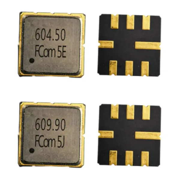
Model Selection
Select by Frequency and Test Definition
The combined FCom datasheet covers 604.5 MHz on page 1 and 609.9 MHz on page 2. Bandwidth definitions and temperature ranges differ; compare each model with its own conditions.
Combined FCom datasheet · Page 1
FSF-5050-604M5
604.5 MHz
Typical center frequency. Uses a 2 dB bandwidth definition and center-frequency loss.
- 2 dB bandwidth
- 5.0 MHz min. / 8.5 MHz typ.
- Loss at 604.5 MHz
- 2.1 dB typ. / 3.0 dB max.
- Operating temperature
- 0 to +50 °C
Insertion loss is specified at the center frequency, not across the full 2 dB bandwidth.
Combined FCom datasheet · Page 2
FSF-5050-609M9
609.9 MHz
Typical center frequency. Uses a 3 dB bandwidth definition and center-frequency loss.
- 3 dB bandwidth
- 5.0 MHz min. / 10.08 MHz typ.
- Loss at 609.9 MHz
- 2.4 dB typ. / 3.5 dB max.
- Operating temperature
- −40 to +85 °C
Insertion loss is specified at the center frequency, not across the full 3 dB bandwidth.
Different bandwidth definitions. The 604.5 MHz model uses a 2 dB bandwidth; the 609.9 MHz model uses a 3 dB bandwidth. Their bandwidth numbers are not a like-for-like comparison, and the models are not established as direct substitutes.
Electrical Specifications
Six Key Parameters, Model by Model
Each model has six key specifications below. Typical values are design guidance; confirm the applicable production limits before release. A dash (—) means not specified or not applicable in that column, not zero.
Scroll horizontally to view all columns.
FSF-5050-604M5 · 604.5 MHz
| Parameter | Min. | Typ. | Max. | Unit | Definition / condition |
|---|---|---|---|---|---|
| Center frequency | — | 604.5 | — | MHz | Typical center frequency |
| Insertion loss at center frequency | — | 2.1 | 3.0 | dB | At 604.5 MHz only |
| 2 dB bandwidth | 5.0 | 8.5 | — | MHz | 2 dB definition |
| Amplitude ripple | — | 0.7 | 1.5 | dB | Over 602–607 MHz |
| Operating temperature | 0 | — | +50 | °C | Operating limits |
| Storage temperature | −40 | — | +85 | °C | Storage limits |
Test source / load: 50 Ω / 50 Ω. Device impedances and measurement temperature are not specified in the supplied FCom table. Ripple test band: 602–607 MHz; this interval is not an alternative name for the 2 dB bandwidth.
FSF-5050-609M9 · 609.9 MHz
| Parameter | Min. | Typ. | Max. | Unit | Definition / condition |
|---|---|---|---|---|---|
| Center frequency | — | 609.9 | — | MHz | Typical center frequency |
| Insertion loss at center frequency | — | 2.4 | 3.5 | dB | At 609.9 MHz only |
| 3 dB bandwidth | 5.0 | 10.08 | — | MHz | 3 dB definition |
| Amplitude ripple | — | 0.2 | 1.0 | dB | Over 608.4–611.4 MHz |
| Operating temperature | −40 | — | +85 | °C | Operating limits |
| Storage temperature | −40 | — | +85 | °C | Storage limits |
Test source / load: 50 Ω / 50 Ω. Device impedances and measurement temperature are not specified in the supplied FCom table. Ripple test band: 608.4–611.4 MHz; this interval is not an alternative name for the 3 dB bandwidth.
Typical Applications
RF/IF Filtering Around the Selected Center Frequency
RF/IF Receiver Stages
Select the 604.5 MHz or 609.9 MHz model to suit the receiver’s frequency plan, then evaluate its bandwidth and center-frequency insertion loss against the system requirements.
UHF Receiver Front Ends
Provide frequency-selective filtering at the chosen model’s operating frequency. Verify rejection, ripple and interface requirements in the intended circuit.
Test and Measurement
Use the appropriate model for signal selection in RF measurement chains. Check the relevant ripple interval and operating temperature for the measurement setup.
Integration Notes
Keep Each Model’s Conditions Separate
Test Terminations and Device Impedance
Both reference measurement circuits use single-ended 50 Ω source and load terminations. These test conditions do not establish a specified 50 Ω device impedance. Evaluate matching with the actual source, load and PCB parasitics; the supplied FCom pages do not provide device impedance values or matching-component values.
Bandwidth and Loss Definitions
Keep center-frequency loss separate from ripple over a band. The lower typical ripple of one model applies to a different frequency interval and does not establish universally better passband performance. The 604.5 MHz model uses a 2 dB bandwidth; the 609.9 MHz model uses a 3 dB bandwidth.
Operating Temperature
Check the temperature requirement before substitution: the 604.5 MHz model is specified for 0 °C to +50 °C, while the 609.9 MHz model is specified for −40 °C to +85 °C. Storage limits do not extend the operating range.
Shared Package and Pins
The supplied FCom pages show the same 5.0 × 5.0 mm, 8-pad SMD package with a maximum height of 1.5 mm. A shared package does not establish electrical interchangeability.
Package & Pin Assignment
5 × 5 mm, 8-Pad SMD Package — Shared Pinout
The supplied FCom pages show the same package dimensions and a maximum height of 1.5 mm for FSF-5050-604M5 and FSF-5050-609M9.
- Body dimensions
- 5.0 × 5.0 mm
- Maximum height
- 1.5 mm
- Package type
- 8-SMD, no lead
Use the corresponding datasheet page to verify mechanical dimensions and pad orientation before layout release. Product photographs are identification views, not PCB footprint drawings. The table retains the FCom Input/Output wording. Contact FCom for other pin configurations.
| Pad(s) | Function |
|---|---|
| 2 | Input/Output |
| 6 | Input/Output |
| 1, 3, 5, 7 | Ground |
| 4, 8 | Case ground |
Selection and Design-In Support
Define the Frequency, Bandwidth and Conditions Together
Include the selected model, required center frequency, bandwidth definition, source and load requirements, operating temperature, sample quantity and estimated usage in your inquiry. Flag any package or pin constraints that affect your design.
The model designations shown here are not a confirmed complete ordering code. Confirm the applicable ordering configuration with FCom before ordering.
Engineering Questions
Frequently Asked Questions
How should I choose between the two models?
Start with the required center frequency and operating temperature. FSF-5050-604M5 is centered at 604.5 MHz and operates from 0 °C to +50 °C. FSF-5050-609M9 is centered at 609.9 MHz and operates from −40 °C to +85 °C. Then assess the separately defined bandwidth, loss and ripple requirements.
Can I compare the 8.5 MHz and 10.08 MHz typical bandwidths directly?
No. The 8.5 MHz typical bandwidth for FSF-5050-604M5 is defined at 2 dB; the 10.08 MHz typical bandwidth for FSF-5050-609M9 is defined at 3 dB. Both have a 5.0 MHz minimum under their own definitions. Do not treat these as equivalent bandwidth limits.
Are the insertion loss limits specified across the ripple bands?
No. Insertion loss is specified at the center frequency: 604.5 MHz or 609.9 MHz. Ripple is specified over 602–607 MHz for FSF-5050-604M5 and 608.4–611.4 MHz for FSF-5050-609M9. The insertion loss limits must not be extended to those entire bands.
Do both devices have a specified 50 Ω impedance?
No. Both are evaluated with 50 Ω source and 50 Ω load test terminations. The supplied FCom datasheet does not specify device input or output impedance. Assess matching against the actual source, load and PCB.
Do the models share a package and pin assignment?
The supplied FCom pages show the same 5.0 × 5.0 mm, 8-pad SMD package with a maximum height of 1.5 mm. Pads 2 and 6 are Input/Output; pads 1, 3, 5 and 7 are ground; pads 4 and 8 are case ground. A shared package does not establish electrical interchangeability.
Which datasheet page and inquiry details apply to my model?
The combined FCom PDF covers FSF-5050-604M5 on page 1 and FSF-5050-609M9 on page 2. For an inquiry, include the model, center frequency, bandwidth definition, source and load requirements, temperature range, sample quantity and estimated usage. Confirm the complete ordering code with FCom.