
FCom Fuji Crystal · FSF-5050 Series
420, 423.75, 424, 426.1 & 427.8 MHz SAW Bandpass Filters
FSF-5050-420M · FSF-5050-423M75 · FSF-5050-424M · FSF-5050-426M1 · FSF-5050-427M8
Five frequency options in the supplied 5.0 × 5.0 mm SMD package, with model-specific passband definitions, matching requirements, DC limits and operating ranges.
427.8 MHz configuration: the balanced electrical data and the supplied FCom pin table require reconciliation. Confirm the balanced pin assignment and data applicability before design use.
Model Selection
Five options. Model-specific conditions.
Compare the definition behind each bandwidth or passband value. Similar frequencies and package dimensions do not establish interchangeability.
2 dB bandwidth
FSF-5050-420M
420 MHz
18 MHz min. / 21.25 MHz typ. — 2 dB bandwidth relative to ILmin
- Insertion loss (ILmin)
- 1.4 dB typ. / 2.8 dB max.
- Operating range
- 0 to +50 °C
- Test termination
- 50 Ω single-ended
- Maximum input
- 10 dBm
- Maximum DC
- 3 V
Specified passband
FSF-5050-423M75
423.75 MHz
Specified passband 421.5–426 MHz; 3 dB bandwidth not specified
- Insertion loss
- 2.0 dB typ. / 3.5 dB max.
- Amplitude ripple
- 0.4 dB typ. / 2.2 dB max.
- Operating range
- −40 to +85 °C
- Test termination
- 50 Ω single-ended
- Maximum DC
- 0 V
2 dB bandwidth
FSF-5050-424M
424 MHz
18 MHz min. / 21.4 MHz typ. — 2 dB bandwidth relative to ILmin
- Insertion loss (ILmin)
- 1.4 dB typ. / 2.8 dB max.
- Operating range
- 0 to +50 °C
- Test termination
- 50 Ω single-ended
- Maximum input
- 20 dBm
- Maximum DC
- 3 V
Specified passband
FSF-5050-426M1
426.1 MHz
Specified passband 426.012–426.150 MHz; 3 dB bandwidth not specified
- Insertion loss
- 2.5 dB typ. / 3.5 dB max.
- Ripple deviation (p-p)
- 0.1 dB typ. / 1.5 dB max.
- Operating range
- −10 to +60 °C
- Test condition
- 50 Ω analyzer with external matching
- Maximum DC
- 5 V
Specified passband
FSF-5050-427M8
427.8 MHz
Specified passband 425.3–430.3 MHz; 3 dB bandwidth not specified
- Insertion loss
- 2.05 dB typ. / 3.6 dB max.
- Amplitude ripple
- 0.65 dB typ. / 2.1 dB max.
- Operating range
- +15 to +35 °C
- Test condition
- 200 Ω balanced electrical data
Balanced pin assignment and applicability require confirmation.
Six key parameters per model
Electrical specifications
“—” means not specified, not zero. Min., Typ. and Max. retain their source meanings. Model-specific test conditions must be retained when evaluating these values.
FSF-5050-420M
Scroll horizontally to view all columns.
| Parameter | Min. | Typ. | Max. | Unit | Definition / condition |
|---|---|---|---|---|---|
| Center frequency | — | 420 | — | MHz | Typical; mean of the frequencies at ILmin + 2 dB |
| Minimum insertion loss, ILmin | — | 1.4 | 2.8 | dB | Minimum passband insertion loss |
| 2 dB bandwidth | 18 | 21.25 | — | MHz | Relative to ILmin |
| Operating temperature | 0 | — | +50 | °C | Operating limits |
| Test source impedance | — | 50 | — | Ω | Single-ended test termination |
| Test load impedance | — | 50 | — | Ω | Single-ended test termination |
ILmin is not a maximum-loss guarantee across the entire bandwidth. No amplitude-ripple limit or reference measurement temperature is specified. Source/load values describe test terminations, not intrinsic device impedances.
FSF-5050-423M75
Scroll horizontally to view all columns.
| Parameter | Min. | Typ. | Max. | Unit | Definition / condition |
|---|---|---|---|---|---|
| Center frequency | — | 423.75 | — | MHz | Typical |
| Specified passband | — | — | — | MHz | 421.5–426 MHz; 3 dB bandwidth not specified |
| Insertion loss | — | 2.0 | 3.5 | dB | 421.5–426 MHz |
| Amplitude ripple | — | 0.4 | 2.2 | dB | 421.5–426 MHz |
| Group delay ripple | — | 55 | 220 | ns | 421.5–426 MHz |
| Operating temperature | −40 | — | +85 | °C | Operating limits |
Source and load test terminations are each 50 Ω, single-ended. The maximum DC voltage is 0 V. No reference measurement temperature is specified. The passband range is not a 3 dB bandwidth.
FSF-5050-424M
Scroll horizontally to view all columns.
| Parameter | Min. | Typ. | Max. | Unit | Definition / condition |
|---|---|---|---|---|---|
| Center frequency | — | 424 | — | MHz | Typical; mean of the frequencies at ILmin + 2 dB |
| Minimum insertion loss, ILmin | — | 1.4 | 2.8 | dB | Minimum passband insertion loss |
| 2 dB bandwidth | 18 | 21.4 | — | MHz | Relative to ILmin |
| Operating temperature | 0 | — | +50 | °C | Operating limits; separate from test temperature |
| Test source impedance | — | 50 | — | Ω | Single-ended test termination |
| Test load impedance | — | 50 | — | Ω | Single-ended test termination |
Electrical data use a 25 °C reference temperature. The operating temperature range is a separate limit. ILmin is not a maximum-loss guarantee across the full bandwidth. No amplitude-ripple limit is specified.
FSF-5050-426M1
Scroll horizontally to view all columns.
| Parameter | Min. | Typ. | Max. | Unit | Definition / condition |
|---|---|---|---|---|---|
| Center frequency | — | 426.1 | — | MHz | Typical |
| Specified passband | — | — | — | MHz | 426.012–426.150 MHz; 3 dB bandwidth not specified |
| Insertion loss | — | 2.5 | 3.5 | dB | 426.012–426.150 MHz |
| Ripple deviation (p-p) | — | 0.1 | 1.5 | dB | 426.012–426.150 MHz |
| Operating temperature | −10 | — | +60 | °C | Operating limits |
| Specified source / load impedance | — | 53 − j29.44 | — | Ω | Each specified termination; distinct from 50 Ω analyzer ports |
The analyzer uses 50 Ω source and load ports with external matching. Each port has a 12 pF series capacitor and a 22 nH shunt inductor to ground on the filter side. No reference measurement temperature or 3 dB bandwidth is specified.
FSF-5050-427M8
Applicability pending: the values below are for balanced testing. They are not established for the single-ended pin configuration retained in the supplied FCom document.
Scroll horizontally to view all columns.
| Parameter | Min. | Typ. | Max. | Unit | Definition / condition |
|---|---|---|---|---|---|
| Center frequency | — | 427.8 | — | MHz | Typical; balanced data, applicability pending |
| Specified passband | — | — | — | MHz | 425.3–430.3 MHz; 3 dB bandwidth not specified |
| Insertion loss | — | 2.05 | 3.6 | dB | 425.3–430.3 MHz; balanced data |
| Amplitude ripple | — | 0.65 | 2.1 | dB | 425.3–430.3 MHz; balanced data |
| VSWR | — | 1.6 | 2.2 | Ratio | 425.3–430.3 MHz; dimensionless |
| Operating temperature | +15 | — | +35 | °C | Operating limits in the supplied document |
These electrical values require 200 Ω balanced source and load terminations. The supplied FCom pin table describes single-ended connections and does not establish the required balanced pin assignment. Confirm the FCom configuration and applicability before using these values in a design. No reference measurement temperature is specified.
All listed stopband attenuation data in the supplied document are absolute, referenced to 0 dB. The 2 dB bandwidths for 420M and 424M instead use ILmin as their reference. Consult the combined FCom PDF for complete model-specific attenuation bands, maximum ratings and storage limits.
Application Fit
Typical applications
RF receiver band selection
Choose the frequency option whose specified signal band, insertion loss and rejection bands meet the receiver requirements. Check the complete model data for the expected interferers.
426.1 MHz signal selection
Evaluate signals within 426.012–426.150 MHz using the specified matching conditions. This is a defined performance interval, not a supplied 3 dB bandwidth.
Balanced RF / IF evaluation
The 427.8 MHz data describe balanced operation. Confirm the applicable FCom balanced pin configuration before evaluating the model in a differential signal path.
Integration Notes
Matching, interfaces and PCB evaluation
420 / 423.75 / 424 MHz
Use the stated 50 Ω single-ended source and load test conditions. These terminations do not specify intrinsic device impedances. The reference measurement circuits show direct connections without external matching components.
For 423M75, the maximum DC voltage is 0 V. Verify DC isolation requirements for the actual circuit. Do not transfer another model’s voltage rating.
426.1 MHz matching
The specified source and load impedances are each 53 − j29.44 Ω. The analyzer ports are 50 Ω. At each filter port, matching consists of a 12 pF series capacitor and a 22 nH shunt inductor to ground on the filter side.
Use the applicable FCom pin assignment and evaluate the network with PCB parasitics. This description is not an independently validated application schematic.
427.8 MHz: confirm the configuration. The electrical values require 200 Ω balanced source and load terminations. The FCom pin table retained in the source instead labels pins 2 and 6 Input/Output and grounds pins 1, 3, 5 and 7. The required balanced FCom pin assignment is unresolved. Do not infer a corrected pinout from another model or apply these values to the supplied single-ended connections without confirmation.
Package and Connections
Package & pin assignment
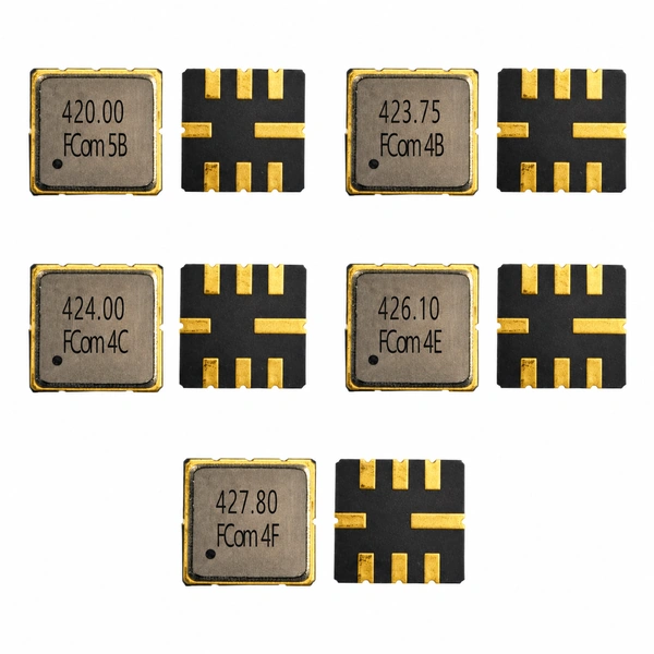
All five supplied FCom pages show a 5.0 × 5.0 mm, 8-pad leadless SMD package with a maximum height of 1.5 mm. Shared outline dimensions do not confirm signal connectivity. Use the applicable FCom drawing and confirm the mounting view before PCB release.
420M / 423M75 / 424M / 426M1
The adjacent table applies to these four models. FCom labels pins 2 and 6 Input/Output; confirm the required direction for the selected configuration.
The photograph identifies product markings and pad sides; it does not establish pad numbering, orientation or polarity. Contact FCom for other pin-configuration requirements.
| Pin(s) | FCom function |
|---|---|
| 2 | Input/Output |
| 6 | Input/Output |
| 1, 3 | Ground |
| 5, 7 | Ground |
| 4 | Case ground |
| 8 | Case ground |
FSF-5050-427M8: the source pin table conflicts with the balanced electrical configuration. A usable balanced FCom pin assignment is not established on this page. Confirm it with FCom before layout or design release.
Selection and Design-In Support
What to include in your inquiry
Provide your selected frequency, required passband and bandwidth definition, source/load conditions, interface type, DC conditions and operating temperature. Include sample quantity and estimated usage.
Confirm the applicable production specification and complete ordering code. For 426M1, include the proposed matching layout; for 427M8, request confirmation of the balanced pin assignment and data applicability.
Engineering Questions
Frequently asked questions
How should I compare the bandwidth specifications?
FSF-5050-420M and FSF-5050-424M specify 2 dB bandwidth relative to ILmin. The 423.75, 426.1 and 427.8 MHz models instead list frequency ranges for specified passband performance; a 3 dB bandwidth is not provided for those models. Do not treat these definitions as interchangeable.
What does the 0 V DC limit mean for FSF-5050-423M75?
The supplied document specifies a maximum DC voltage of 0 V. Check the DC conditions at the filter connections and any required isolation before design release. Do not apply the 3 V or 5 V ratings of other models to this part.
What matching is specified for FSF-5050-426M1?
The supplied FCom data list source and load impedances of 53 − j29.44 Ω each, distinct from the 50 Ω analyzer ports. At each filter port the test network uses a 12 pF series capacitor and a 22 nH shunt inductor to ground on the filter side. Evaluate this configuration with the applicable FCom drawing and actual PCB.
Can I use the listed 427.8 MHz data with the supplied FCom pin table?
Not as a confirmed design configuration. The electrical values require 200 Ω balanced source and load terminations, while the supplied FCom pin table describes single-ended connections. The balanced pin assignment and applicability of the electrical values must be confirmed with FCom before design use.
Are the models interchangeable or tested at the same temperature?
Interchangeability is not established. Bandwidth definitions, passbands, DC limits, matching, interfaces and operating temperatures differ. A 25 °C electrical reference temperature is stated only for FSF-5050-424M in the supplied FCom pages. Operating ranges must not be substituted for test temperatures or storage ranges.
What should I include in an inquiry?
Provide the selected model or frequency, required passband and bandwidth definition, source/load requirements, single-ended or balanced interface, DC conditions, operating temperature, sample quantity and estimated usage. For FSF-5050-427M8, request confirmation of the balanced pin assignment and electrical applicability. Confirm the complete ordering code before ordering.