
FCom Fuji Crystal · Miniature CSP SAW Filters
Miniature GPS & GNSS SAW Filters — FSF-1109/1411
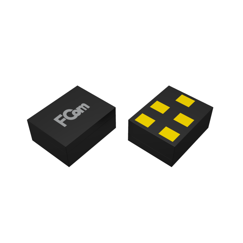
CSP · 1.1 × 0.9 mm / 1.4 × 1.1 mm
Select a miniature GPS SAW filter for a 1575.42 MHz L1 or 1176.45 MHz L5 receiver path. Compare FSF-1109 and FSF-1411 options by center frequency, bandwidth, CSP package, insertion loss and stopband attenuation. The full catalog includes 64 models for GNSS and other compact RF designs.
Receiver Front-End Selection
Choose a GPS L1, L5 or GNSS SAW Filter
GPS L1 · 1575.42 MHz
Evaluate the 1575.42 MHz FSF-1411 option for GPS L1. Compare the model’s datasheet response with the receiver’s required passband around 1575 MHz.
GPS L5 · 1176.45 MHz
Compare the 1176.45 MHz models in CSP1109 and CSP1411. Both list 20 MHz bandwidth. Check the exact package drawing, matching circuit and guaranteed response before layout.
GNSS Band and Channel Selection
Define the signals and passband required for each receiver path. Compare model-specific insertion loss, rejection at interfering frequencies and impedance. For a GLONASS design around 1602 MHz, start with the FSF-3030 1602 MHz catalog option and verify the channels and passband in its datasheet.
Automotive GPS SAW Filter Selection
For automotive positioning or telematics, confirm the operating temperature, electrical limits and required qualification documentation for the exact part number. Verify the filter response with the intended antenna, LNA and receiver interface.
Model Catalog
Compare All 64 FSF-1109/1411 Models
Compare each part number and its listed center frequency, bandwidth, package, insertion loss and stopband attenuation. The L1 and L5 models appear first. The remaining models follow in ascending center-frequency order.
Scroll within the table or use your browser’s Find command. Click a part number to request its datasheet by email.
| Complete P/N | CSP Package | Center Frequency (MHz) | Listed Bandwidth (MHz) | Listed Insertion Loss (dB) | Listed Stopband Attenuation (dB) |
|---|---|---|---|---|---|
| GPS L1 · 1575.42 MHz | |||||
| FSF1411-1575M42-2M4-1.1-40 | CSP14111.4 × 1.1 mm | 1575.42 | 2.4 | 1.1 | 40.0 |
| GPS L5 · 1176.45 MHz | |||||
| FSF1109-1176M45-20M-1.4-40 | CSP11091.1 × 0.9 mm | 1176.45 | 20.0 | 1.4 | 40.0 |
| FSF1411-1176M45-20M-1.4-40 | CSP14111.4 × 1.1 mm | 1176.45 | 20.0 | 1.4 | 40.0 |
| Other Catalog Center Frequencies | |||||
| FSF1109-707M-17M-2-30 | CSP11091.1 × 0.9 mm | 707.0 | 17.0 | 2.0 | 30.0 |
| FSF1109-742M5-27M-2.5-50 | CSP11091.1 × 0.9 mm | 742.5 | 27.0 | 2.5 | 50.0 |
| FSF1411-780M5-45M-1.6-40 | CSP14111.4 × 1.1 mm | 780.5 | 45.0 | 1.6 | 40.0 |
| FSF1411-782M-12M-1.6-40 | CSP14111.4 × 1.1 mm | 782.0 | 12.0 | 1.6 | 40.0 |
| FSF1109-836M-25M-2-40 | CSP11091.1 × 0.9 mm | 836.0 | 25.0 | 2.0 | 40.0 |
| FSF1411-836M-25M-2-40 | CSP14111.4 × 1.1 mm | 836.0 | 25.0 | 2.0 | 40.0 |
| FSF1411-847M-30M-1.6-40 | CSP14111.4 × 1.1 mm | 847.0 | 30.0 | 1.6 | 40.0 |
| FSF1109-876M5-35M-2-40 | CSP11091.1 × 0.9 mm | 876.5 | 35.0 | 2.0 | 40.0 |
| FSF1109-881M5-25M-1.5-40 | CSP11091.1 × 0.9 mm | 881.5 | 25.0 | 1.5 | 40.0 |
| FSF1411-881M5-25M-2.3-30 | CSP14111.4 × 1.1 mm | 881.5 | 25.0 | 2.3 | 30.0 |
| FSF1109-897M5-30M-2.5-40 | CSP11091.1 × 0.9 mm | 897.5 | 30.0 | 2.5 | 40.0 |
| FSF1109-897M5-35M-2-40 | CSP11091.1 × 0.9 mm | 897.5 | 35.0 | 2.0 | 40.0 |
| FSF1411-897M5-30M-2.5-40 | CSP14111.4 × 1.1 mm | 897.5 | 30.0 | 2.5 | 40.0 |
| FSF1411-897M5-35M-2-40 | CSP14111.4 × 1.1 mm | 897.5 | 35.0 | 2.0 | 40.0 |
| FSF1411-911M5-27M-1.6-40 | CSP14111.4 × 1.1 mm | 911.5 | 27.0 | 1.6 | 40.0 |
| FSF1109-915M-26M-1.5-50 | CSP11091.1 × 0.9 mm | 915.0 | 26.0 | 1.5 | 50.0 |
| FSF1411-915M-26M-1.5-50 | CSP14111.4 × 1.1 mm | 915.0 | 26.0 | 1.5 | 50.0 |
| FSF1109-942M5-35M-2.2-40 | CSP11091.1 × 0.9 mm | 942.5 | 35.0 | 2.2 | 40.0 |
| FSF1411-942M5-35M-2.2-40 | CSP14111.4 × 1.1 mm | 942.5 | 35.0 | 2.2 | 40.0 |
| FSF1109-1197M-62M4-1.3-20 | CSP11091.1 × 0.9 mm | 1197.0 | 62.4 | 1.3 | 20.0 |
| FSF1411-1202M-72M-2.4-30 | CSP14111.4 × 1.1 mm | 1202.0 | 72.0 | 2.4 | 30.0 |
| FSF1109-1268M52-20M46-1.7-40 | CSP11091.1 × 0.9 mm | 1268.52 | 20.46 | 1.7 | 40.0 |
| FSF1411-1561M89-21M-3.3-40 | CSP14111.4 × 1.1 mm | 1561.089 | 21.0 | 3.3 | 40.0 |
| FSF1411-1568M-18M32-1.6-40 | CSP14111.4 × 1.1 mm | 1568.0 | 18.32 | 1.6 | 40.0 |
| FSF1411-1573M-66M-2.8-30 | CSP14111.4 × 1.1 mm | 1573.0 | 66.0 | 2.8 | 30.0 |
| FSF1109-1582M4-46M-0.9-40 | CSP11091.1 × 0.9 mm | 1582.4 | 46.0 | 0.9 | 40.0 |
| FSF1109-1582M4-46M-1.8-40 | CSP11091.1 × 0.9 mm | 1582.4 | 46.0 | 1.8 | 40.0 |
| FSF1411-1582M4-46M-1.8-40 | CSP14111.4 × 1.1 mm | 1582.4 | 46.0 | 1.8 | 40.0 |
| FSF1411-1600M-40M-1.9-40 | CSP14111.4 × 1.1 mm | 1600.0 | 40.0 | 1.9 | 40.0 |
| FSF1411-1603M-12M-2.3-40 | CSP14111.4 × 1.1 mm | 1603.0 | 12.0 | 2.3 | 40.0 |
| FSF1411-1637M-2M-2-40 | CSP14111.4 × 1.1 mm | 1637.0 | 2.0 | 2.0 | 40.0 |
| FSF1109-1745M5-70M-1.8-30 | CSP11091.1 × 0.9 mm | 1745.5 | 70.0 | 1.8 | 30.0 |
| FSF1411-1745M5-70M-1.8-30 | CSP14111.4 × 1.1 mm | 1745.5 | 70.0 | 1.8 | 30.0 |
| FSF1109-1747M5-75M-1.3-30 | CSP11091.1 × 0.9 mm | 1747.5 | 75.0 | 1.3 | 30.0 |
| FSF1109-1747M5-75M-2.1-30 | CSP11091.1 × 0.9 mm | 1747.5 | 75.0 | 2.1 | 30.0 |
| FSF1411-1800M-40M-2-40 | CSP14111.4 × 1.1 mm | 1800.0 | 40.0 | 2.0 | 40.0 |
| FSF1109-1842M5-65M-2-40 | CSP11091.1 × 0.9 mm | 1842.5 | 65.0 | 2.0 | 40.0 |
| FSF1109-1842M5-75M-1.5-30 | CSP11091.1 × 0.9 mm | 1842.5 | 75.0 | 1.5 | 30.0 |
| FSF1109-1842M5-75M-2.5-40 | CSP11091.1 × 0.9 mm | 1842.5 | 75.0 | 2.5 | 40.0 |
| FSF1109-1880M-60M-2.2-30 | CSP11091.1 × 0.9 mm | 1880.0 | 60.0 | 2.2 | 30.0 |
| FSF1411-1880M-60M-2.2-30 | CSP14111.4 × 1.1 mm | 1880.0 | 60.0 | 2.2 | 30.0 |
| FSF1109-1900M-40M-1.7-30 | CSP11091.1 × 0.9 mm | 1900.0 | 40.0 | 1.7 | 30.0 |
| FSF1109-1950M-60M-1.6-30 | CSP11091.1 × 0.9 mm | 1950.0 | 60.0 | 1.6 | 30.0 |
| FSF1109-2140M-60M-1.8-40 | CSP11091.1 × 0.9 mm | 2140.0 | 60.0 | 1.8 | 40.0 |
| FSF1109-2155M-90M-2.6-30 | CSP11091.1 × 0.9 mm | 2155.0 | 90.0 | 2.6 | 30.0 |
| FSF1109-2350M-100M-2.3-30 | CSP11091.1 × 0.9 mm | 2350.0 | 100.0 | 2.3 | 30.0 |
| FSF1109-2437M-69M-1.1-30 | CSP11091.1 × 0.9 mm | 2437.0 | 69.0 | 1.1 | 30.0 |
| FSF1109-2442M-79M-1.2-40 | CSP11091.1 × 0.9 mm | 2442.0 | 79.0 | 1.2 | 40.0 |
| FSF1411-2442M-79M-1.3-40 | CSP14111.4 × 1.1 mm | 2442.0 | 79.0 | 1.3 | 40.0 |
| FSF1411-2442M-79M-2-40 | CSP14111.4 × 1.1 mm | 2442.0 | 79.0 | 2.0 | 40.0 |
| FSF1109-2492M-8M-6.5-30 | CSP11091.1 × 0.9 mm | 2492.0 | 8.0 | 6.5 | 30.0 |
| FSF1109-2535M-70M-2-30 | CSP11091.1 × 0.9 mm | 2535.0 | 70.0 | 2.0 | 30.0 |
| FSF1109-2593M-194M-2.1-40 | CSP11091.1 × 0.9 mm | 2593.0 | 194.0 | 2.1 | 40.0 |
| FSF1109-2593M-194M-2.2-40 | CSP11091.1 × 0.9 mm | 2593.0 | 194.0 | 2.2 | 40.0 |
| FSF1411-2593M-194M-2.2-40 | CSP14111.4 × 1.1 mm | 2593.0 | 194.0 | 2.2 | 40.0 |
| FSF1109-2595M-120M-1.6-30 | CSP11091.1 × 0.9 mm | 2595.0 | 120.0 | 1.6 | 30.0 |
| FSF1109-2595M-120M-2.5-30 | CSP11091.1 × 0.9 mm | 2595.0 | 120.0 | 2.5 | 30.0 |
| FSF1411-2595M-160M-1.5-40 | CSP14111.4 × 1.1 mm | 2595.0 | 160.0 | 1.5 | 40.0 |
| FSF1411-2595M-160M-2.5-40 | CSP14111.4 × 1.1 mm | 2595.0 | 160.0 | 2.5 | 40.0 |
| FSF1109-2655M-70M-2-30 | CSP11091.1 × 0.9 mm | 2655.0 | 70.0 | 2.0 | 30.0 |
| FSF1411-3500M-200M-2-40 | CSP14111.4 × 1.1 mm | 3500.0 | 200.0 | 2.0 | 40.0 |
Catalog values support preliminary selection. Confirm bandwidth definitions, minimum, typical and maximum limits, rejection frequency intervals, source/load conditions, measurement temperature and operating limits in the latest model-specific datasheet.
For FSF1411-1561M89-21M-3.3-40, the catalog lists a center frequency of 1561.089 MHz. Confirm the ordering code and center frequency with FCom before ordering.
Selection Notes
Compare the Parameters That Matter
Frequency and Bandwidth
Choose the center frequency and bandwidth that match your signal requirements. Use the selected model’s datasheet to review its bandwidth definition and specified passband.
Loss and Rejection
Evaluate insertion loss against your signal budget and stopband attenuation against your rejection mask, using the frequency intervals and test conditions specified for the model.
Package and Interface
Select the CSP package that fits your layout, then review the pin assignment, source and load conditions, and matching requirements for the complete part number.
Integration Notes
Plan the Electrical and PCB Interface
Source, Load and Matching
Use the model-specific electrical interface and recommended matching arrangement when evaluating the filter. Package size and center frequency alone do not determine the required termination or matching components.
PCB and Operating Conditions
Review the package drawing, land pattern, grounding and assembly requirements before PCB layout. Evaluate the selected filter under your application’s signal and operating conditions.
Package Options
Two Miniature CSP Formats
FSF-1109
- Package
- CSP1109
- Package size
- 1.1 × 0.9 mm
- Mounting
- SMD
- Models in this collection
- 35
FSF-1411
- Package
- CSP1411
- Package size
- 1.4 × 1.1 mm
- Mounting
- SMD
- Models in this collection
- 29
Use the mechanical drawing for the selected part number to establish package height, dimensional tolerances, viewing direction, pin functions and the recommended land pattern.
Selection and Design-In Support
Discuss Your Filter Requirements
For model selection and design-in support, send FCom the complete part number, target passband, insertion-loss budget, rejection requirements, source and load conditions, operating temperature and expected quantity.
Engineering Questions
Frequently Asked Questions
Which center frequencies should I compare for GPS L1 and L5?
Use the 1575.42 MHz L1 and 1176.45 MHz L5 groups in the model table. Confirm each model’s specified passband, loss and rejection against the receiver path.
How do I select a SAW filter for a multiband GNSS receiver?
List the required signals for each receiver path and verify the passband and rejection mask against each selected part’s datasheet. The center frequency and listed bandwidth describe the individual catalog model. Confirm every required band in the receiver’s filter plan.
What frequency options are included in this collection?
This collection includes 64 models with center frequencies from 707 to 3500 MHz. These are individual frequency options; the overall range does not represent a continuous passband or availability at every frequency.
How do the FSF-1109 and FSF-1411 series differ?
FSF-1109 models use a 1.1 × 0.9 mm CSP package, while FSF-1411 models use a 1.4 × 1.1 mm CSP package. Both are surface-mount devices. Compare the complete part number and electrical specifications when selecting a model.
Can models with the same center frequency be used interchangeably?
A shared center frequency does not establish interchangeability. Bandwidth, insertion loss, stopband attenuation, package dimensions, pin assignments and matching requirements should be reviewed for the exact models.
How should I interpret the bandwidth and attenuation values?
Use the catalog values for initial comparison. Refer to the model-specific datasheet for the bandwidth criterion, insertion-loss limits, rejection frequency intervals, source and load conditions, and measurement temperature.
How can I obtain a model-specific datasheet?
Click the required part number to prepare a datasheet inquiry to FCom. Include your application, passband and rejection requirements, source and load conditions, operating temperature and expected quantity.